Word count: 2645. Estimated reading time: 13 minutes.
- Summary:
- The author has been unemployed for seven months and has made good progress on their todo list, which they had built up over eight years. They have visited people, gone to places, and cleared four A4 pages worth of chore and backlog items. Their productivity during unemployment has increased, possibly due to the lack of work-related stress. The author is now nearing completion of their todo list and plans to update their CV soon.
Friday 16 January 2026: 22:05.
- Summary:
- The author has been unemployed for seven months and has made good progress on their todo list, which they had built up over eight years. They have visited people, gone to places, and cleared four A4 pages worth of chore and backlog items. Their productivity during unemployment has increased, possibly due to the lack of work-related stress. The author is now nearing completion of their todo list and plans to update their CV soon.
I’m now into the final A4 page of todo items! To be honest, I’ve not been trying too hard to find new employment, I haven’t been actively scanning the job listings and applying for roles. That will probably change soon – as part of clearing my multi-page todo list I finally got the ‘kitchen sink’ CV brought up to date which took a surprising number of hours of time as I hadn’t updated it since 2020. And, as the kitchen sink CV, it needed absolutely everything I’d done in the past five years, which it turns out was not nothing even though my tech related output is definitely not what it was since I’ve had children. So it did take a while to write it all up.
Still, I have a few more months of todo list item clearance to go yet! The next todo item for this virtual diary is the insulated foundations design for my house build which my structural engineer completed end of last November. I’ll also be getting into my 3D printed model houses as I’ve completed getting them wired up with lights.
To recount the overall timeline to date:
- 2020: We start looking for sites on which to build.
- Aug 2021: We placed an offer on a site.
- Jul 2022: Planning permission obtained (and final house design known).
- Feb 2023: Chose a builder.
- Feb 2024: Lost the previous builder, had to go get a new builder and thus went back to the end of the queue.
- Aug 2024: First draft of structural engineering design based on the first draft of timber frame design.
- Nov 2024: Completed structural engineering design, began joist design.
- Mar 2025: Completed joist design, began first stage of builder’s design sign off.
- Jun 2025: First stage of builder’s design signed off. Structural engineering detail begins.
- Nov 2025: Structural engineering detail is completed, and signed off by me, architect, and builder.
- Dec 2025: Builder supplies updated quote for substructure based on final structural engineering detail (it was approx +€20k over their quote from Feb 2024).
- We await the builder supplying an updated quote for superstructure … I ping him weekly.
We are therefore on course to be two years since we hired this builder, and we have yet to get them to build anything. As frustrating as that is, in fairness they haven’t dropped us yet like the previous builder, and I’m sure all this has been as frustrating and tedious for them as it has been for us. As we got planning permission in July 2022, we are running out of time to get this house up – the planning permission will expire in July 2027 by which time we need to be moved in.
All that said, I really, really, really hope that 2026 sees something actually getting constructed on my site. I was originally told Autumn 2024, we’re now actually potentially Autumn 2026. This needs to end at some point with some construction of a house occurring.
The insulated foundations detail
I last covered the engineer’s design in the June 2025 post, comparing it to the builder’s design and the architect’s design. Though, if you look at the image below it’s just a more detailed version of the image in the August 2024 post. Still, with hindsight, those were designs, but not actual detail. Here is what actual detail looks like:
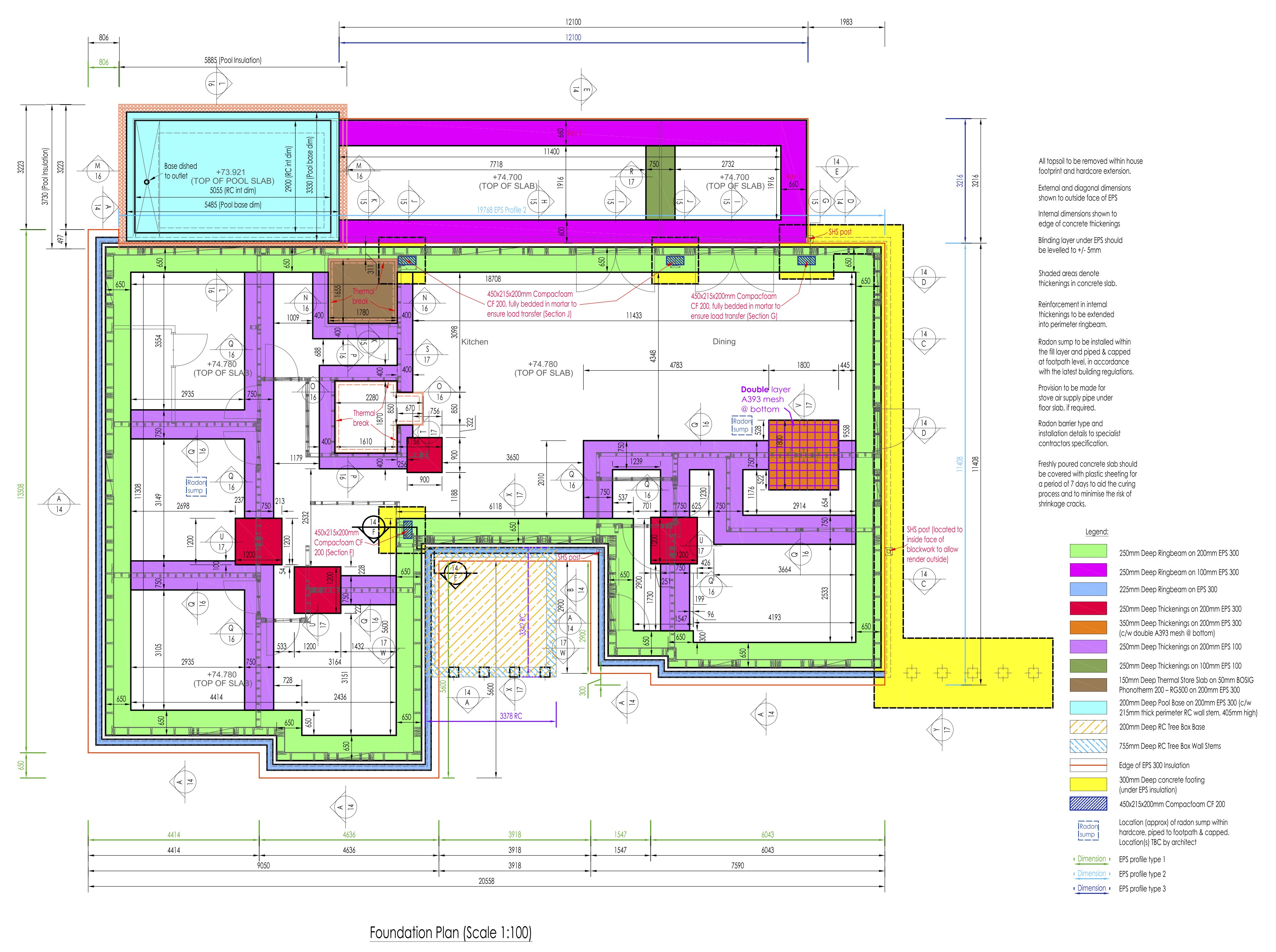
We have lots of colour coded sections showing type and thickness of:
- Ring beams (these support the outer concrete block leaf and outer walls)
- Thickenings (these support internal wall and point loads)
- Footings (these support the above two)
As you can see, the worst point load lands in the ensuite bathroom to the master bedroom – two steel poles bear down on 350 mm extra thick concrete slab with three layers of steel mesh within, all on top of an over sized pad to distribute that point load. This is because the suspended rainwater harvesting tanks have one corner landing there, plus one end of the gable which makes up the master bedroom. The next worst point loads are under the four bases of the steel portal frames, though one is obviously less loaded than the other three (which makes sense, only a single storey flat roof is on that side of that portal frame). And finally, there is a foot of concrete footing – effectively a strip foundation – all around the walls of the right side of the building, this is again to support the suspended rainwater harvesting tanks.
Let’s look at a typical outer wall detail:
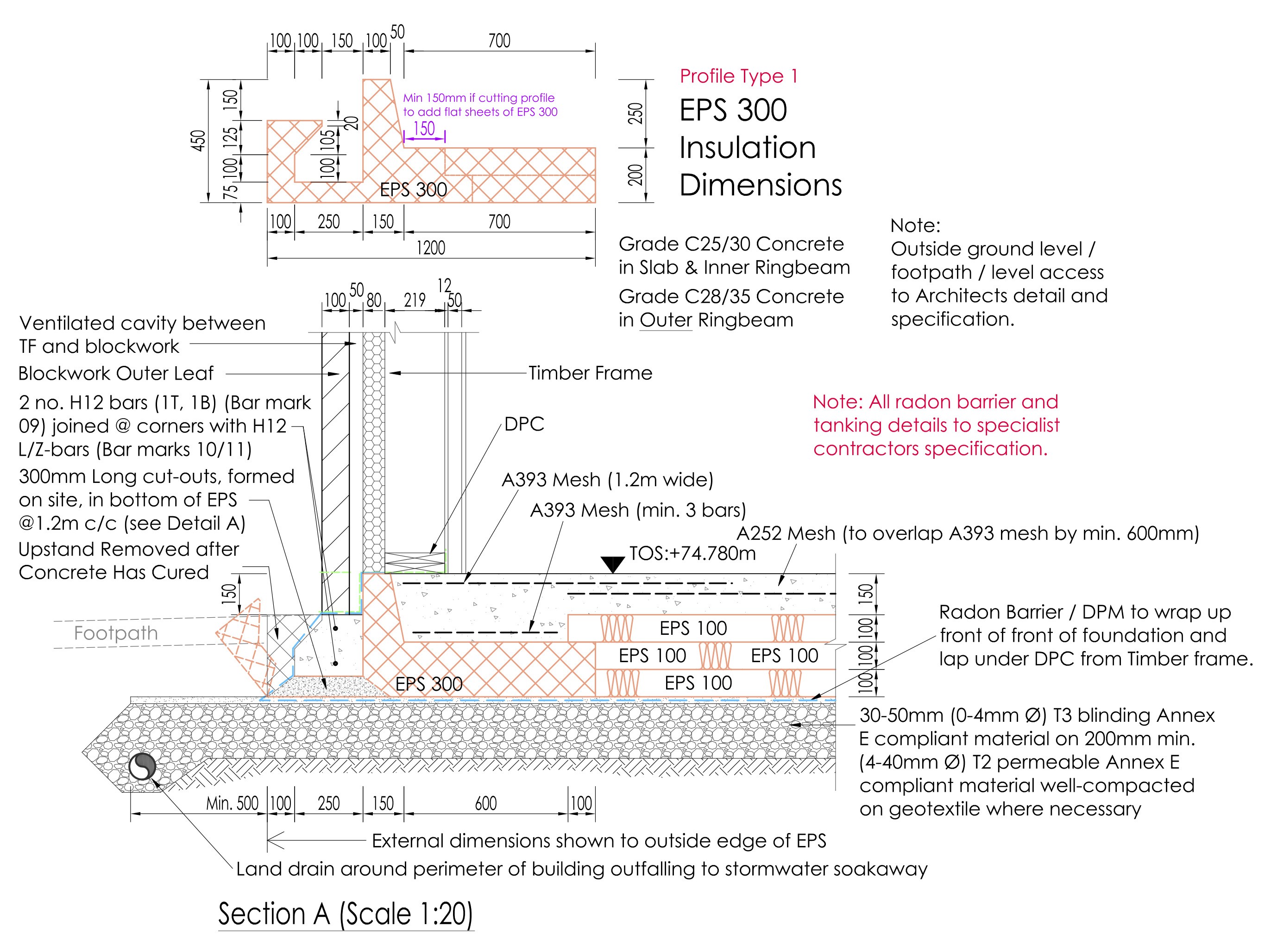
Unsurprisingly, this is identical to the standard KORE agrément requirements diagram I showed in the most recent post about the Outhouse design (and which I still think is overkill for a timber frame house load, but my structural engineer has no choice if we are to use the KORE insulated foundations system). Let’s look at something which we haven’t seen before:
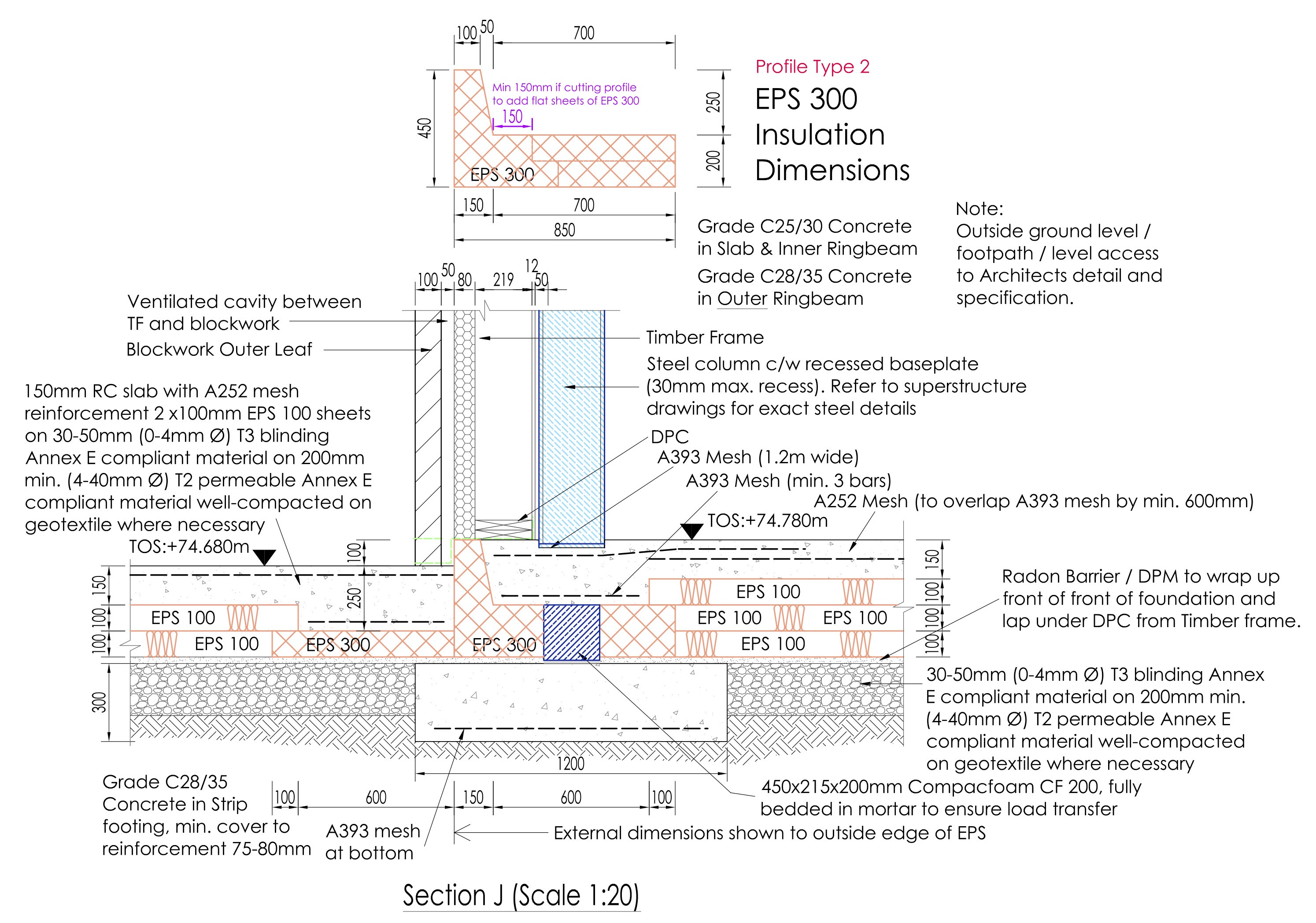
This is for one of the legs of the portal frame next to the greenhouse foundation, which has 200 mm instead of 300 mm of insulation. Much of the weight of the house bears down on those four portal frame legs, so unsurprisingly at the very bottom there is firstly a strip footing, then a block of CompacFoam which can take approx 20x more compressive load than EPS300, then 250 mm of double mesh reinforced concrete slab – you might see a worst case 3000 kPa of point load here, which is of course approximately 300 metric tonnes per sqm. I generally found a safety factor of 3x to 10x depending on where in their design, so I’m guessing that they’re thinking around 100 metric tonnes might sometimes land on each portal frame foot.
Actually, I don’t have to guess, as they supplied a full set of their workings and calculations. I can tell you they calculated ~73 kg/sqm for the timber frame external wall and internal floor, and ~42 kg/sqm for internal racking walls. The roof they calculated as ~140 kg/sqm, as I had said I was going to use concrete tiles. Given these building fabric areas:
- 150 sqm of internal floor = 11 tonnes
- 393 sqm of external wall = 29 tonnes
- 270 sqm of roof = 48 tonnes
… then you get 88 tonnes excluding the internal racking walls, most of which bear onto the concrete slab rather than onto the portal frames. So let’s say a total of 100 tonnes of superstructure. As you can see, even if the entire house were bearing on a single portal frame leg instead of across all four legs, you’d still have a 3x safety margin. With all four portal frame legs, the safety margin is actually 12x.
Speaking of heavy weights, we have a hot 3000 litre thermal store tank to support where the foundation must deal with ~80 C continuous heat. EPS doesn’t like being at 80 C continuously, so if we had hot concrete directly touching the EPS, we were going to have longevity problems. This did cause some thinking caps to be put on by engineer, architect and myself and we came up with this:
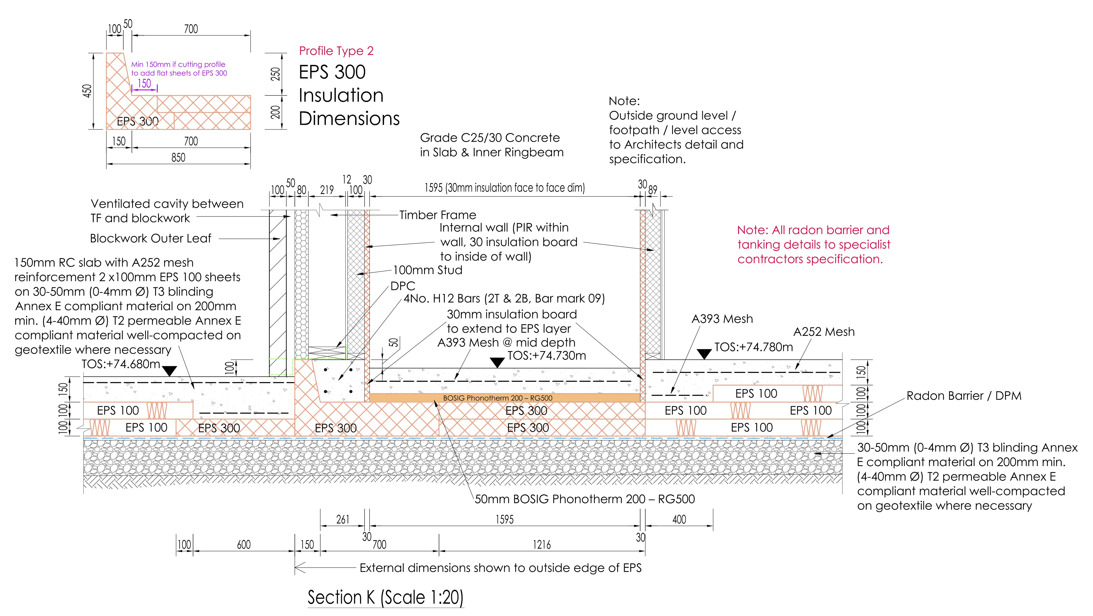
As you see, we introduce a thermal break between the hot concrete slab and the EPS using 50 mm of Bosig Phonotherm, which is made out of polyurethane hard foam. Polyurethane is happy with continuous temperatures of 90 C, and it drops the maximum temperature that the EPS sees to around 70 C. It is also happy getting wet, it can take plenty of compressive loads, and its only real negative is that it is quite expensive. Unfortunately, I’m going to have to use a whole bunch of Bosig Phonotherm all around the window reveals, but apart from the expense it is great stuff to work with and it performs excellently. To the sides, the thermal break is the same 30 mm Kingspan Sauna Satu board which is the first layer of insulation within the thermal store box: Satu board is a specially heat resistant PIR board, and as it is expensive we use conventional PIR board for most of the thermal store insulation. Similar to the Bosig Phonotherm, the Satu board brings the temperature down for the outer PIR, also to about 70 C.
Finally, let’s look at some detail which also delayed the completion of this insulated foundation design: the insulated pool cavity:
The challenge here was to maintain 200 mm of unbroken EPS all the way round whilst also handling the kind of weight that 1.4 metres of water and steel tank and the surrounding soil and pressure from the house foundations will load onto your slab. Solving this well certainly consumed at least six weeks of time, but I think the job well done. Given that my engineer did not charge me more than his original quote – and he certainly did more work than he anticipated at the beginning – I cannot complain. The quality of work is excellent, and I’m glad that this part of the house design has shipped finally.
3D printed model house
Eighteen months ago I taught myself enough 3D printing design skills that I was able to print my future house using my budget 3D printer. It came out well enough that I ordered online a much bigger print in ivory coloured ASA plastic, which I wrote about here back in June 2024. In that post, I demonstrated remarkable self knowledge by saying:
When all the bits arrive, if a weekend of time appears, I’ll get it all cut out, slurry paste applied where it is needed, wired up and mounted and then put away into storage. Or, I might kick it into the long touch as well and not get back to it for two years. Depends on what the next eighteen months will be like.
Writing now eighteen months later … indeed. After the model arrived, I then ordered a case for it which I wrote here about in August 2024, where I wrote:
The extra height of the case will be used by standing each layer of the house on stilts, with little LED panels inside lighting the house. You’ll thus be able to see all around the inside of the model house whilst standing instead the actual finished house. It may well be a decade before I get to assemble all the parts to create the final display case, or if this build takes even longer I might just get it done before the build starts. We’ll see.
I was being overly pessimistic I think by this point, though had the house build started sometime between then and now maybe I’d be too occupied working on the house to work on a model house. Anyway, all that’s moot, because witness the awesomeness of the fully operational house model:
From all sides:

And with the case on:

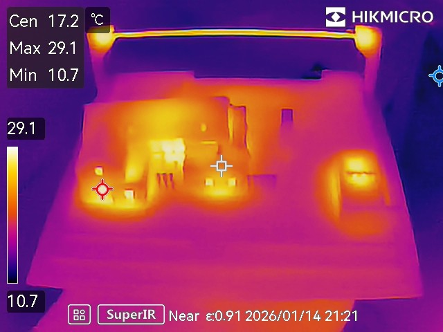
To make sure there would be no thermal runaway problems which might melt the house etc:
Looks like on full power after twenty minutes with the case on we get a maximum 54 C or so. Now, it being winter here, the surroundings are cold so that could easily be 10-15 C more in summer. But it wouldn’t matter – ASA plastic has a glass transition temperature of 100 C. And, besides, we’ll never run the lights at full power, they’re too bright so they will be at most on a 33% PWM dimming cycle.
The lighting is provided by these COB LED strips with integrated aluminium heatsink made by a Chinese vendor called Sumbulbs. You can find them in all the usual places and you can buy a dozen of them for a few euro delivered. They are intended to be soldered, and you can see my terrible soldering skills at work:
The layers of the house are separated by cake stands:
And with the case on:
And finally, showing both the cake stands and the COB LED light strips:
You’ll note that not all the COB LED strips have the same brightness. With hindsight, this is very obvious – that darker one to the bottom right clearly has only a few LEDs spaced well apart, whereas the top roof ones especially are densely packed LEDs. I mainly chose the strips at the time based on what would fit the space available rather than any other consideration. Anyway, I don’t think it matters hugely, but perhaps something to be considered by anybody reading this.
In case you’re wondering, total costs were:
- €150 inc VAT inc delivery for the 3D print.
- €200 inc VAT inc delivery for the cases (this includes the small case below).
- €20 inc VAT inc delivery for the cake stands, most of which I did not use.
- €10 inc VAT inc delivery for the COB LED strips, and I also only ended up using a few of these and I have loads spare.
So I’d make that about €350 inc VAT inc delivery, plus a whole load of my time to design the 3D print and do all the wiring. I intend to mount it into the ‘house mini museum’ which will memorialise how the house was designed and built.
3D printed model site
You may or may not remember that using my own personal 3D printer I had also printed the whole site. This isn’t very big as it’s limited by the 20 cm x 20 cm maximum plate on my personal 3D printer, but it gives you a good sense of how the house and outhouse frame the site. Anyway, I started by inserting 4 mm LEDs throughout the house and outhouse:
I also designed a little stand for ‘the sun’ at the south side of the site, which is another Sumbulbs COB LED strip with integrated aluminium heatsink (the same used throughout the big house model):
And turning up ‘the sun’ to full power:
With the roofs off:
And finally the thermals:
Once again, no issue there even on full power with the case on after twenty minutes.
This model certainly cost under €50 inc VAT inc delivery, maybe €40 is a reasonable estimate. Most of the cost was the case, and of course my time.
My plan for this model is that it will be in daylight when it is daylight outside, and go to night time when it is night time outside, and it’ll also be mounted in the mini house museum. Should be very straightforward. Just need to get the real house built.
I continue to ping the builder weekly, and maybe at some point he might pony up a final quote and then it’ll be off to the races after two years with him, and three years waiting for builders in general. Here’s hoping!
| Go to previous entry | Go to next entry | Go back to the archive index | Go back to the latest entries |