Word count: 2401. Estimated reading time: 12 minutes.
- Summary:
- The Olimex ESP32-POE board has been running reliably for several months, with its three sensors posting readings to an Influx DB every few seconds. The board’s PoE circuit runs hot, but the temperature is well below the rating of its industrial-grade components. The ESPHome firmware has made it easy to integrate the board into a larger system, and its features have been a game-changer for my use case.
Friday 21 October 2022: 23:43.
- Summary:
- The Olimex ESP32-POE board has been running reliably for several months, with its three sensors posting readings to an Influx DB every few seconds. The board’s PoE circuit runs hot, but the temperature is well below the rating of its industrial-grade components. The ESPHome firmware has made it easy to integrate the board into a larger system, and its features have been a game-changer for my use case.
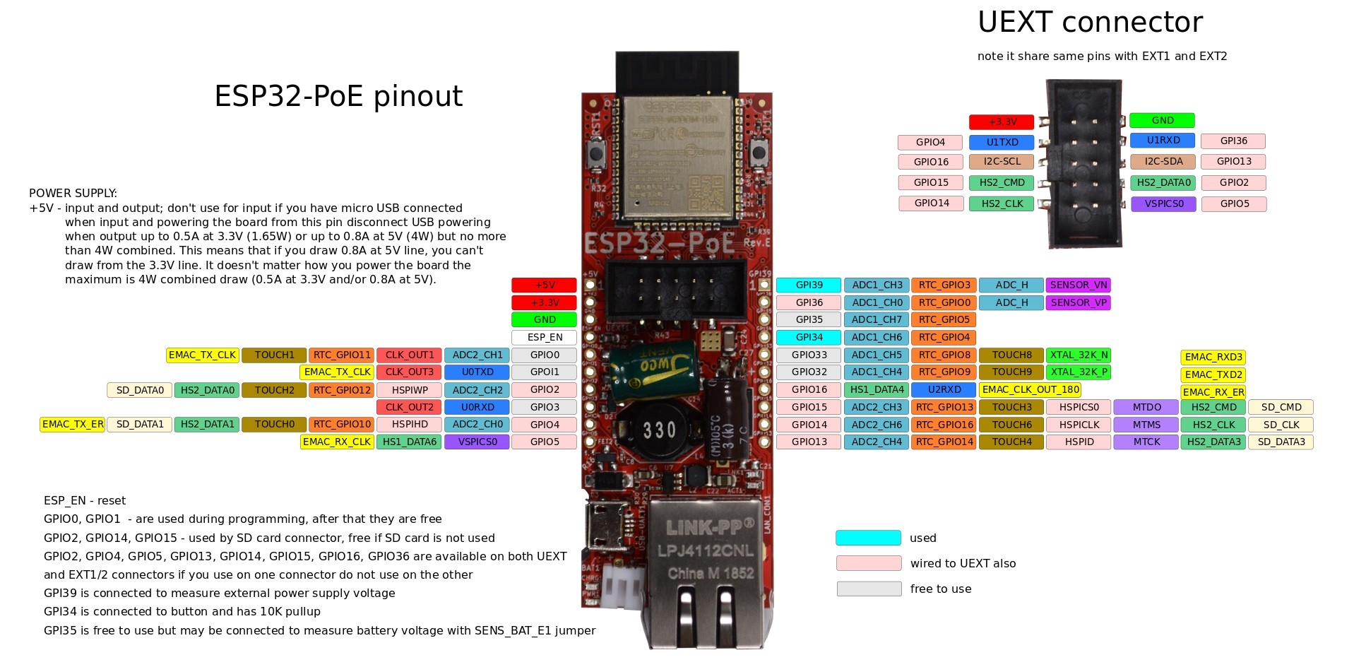
Here is the board I dropped about a grand upon buying fifty of them plus convenience breakouts:
You may remember that a year ago I was not keen on the ESP32, as it is markedly inferior to the STM32F4 in terms of quality and quirks, albeit with bucket loads more features. So why change my mind now?
First reason is cost: when you’re spending a grand of money, saving a third of it is a good move. In my Q3 2021 review post, I reckoned a STM32F4 could be had for €12 inc VAT and a Raspberry Pi for €20 inc VAT, but that didn’t include the PoE adapter which probably can’t be had for less than €10 inc VAT. The Olimex ESP32-POE-IND (with industrial grade components) is under €15 inc VAT if you buy fifty of them, which is nearly one third cheaper.
The second reason is convenience: These boards have already wired a bunch of stuff together for me into a single PCB, which saves me having to wire bits together. Its premounted UEXT connector exposes the UART, I2C and SPI pins plus 3.3v power which will save me soldering in i/o pins in many cases (I also bought a bunch of UEXT daisy chain boards, they were very cheap and let me use dupont wiring instead of hand soldering and crimping). They’re correspondingly more compact, which means I can use smaller much cheaper waterproof enclosures, saving even more money.
The third reason is that for all the things the ESP32 is bad at e.g. Analogue to Digital conversion, or keeping accurate time – I can cheaply buy an I2C peripheral which does have quality ADCs, or quality time. And it’s only rarely I’ll need to do that in any case as the majority of those boards will go on PWM control of RGBWW LED strips. The PWM in the ESP32 isn’t as good as the one in the STM32F4 or the Raspberry Pi, but it can still push 15kHz, which is plenty. One of these boards can PWM up to three LED strips (four channels each, therefore twelve I/Os) if I solder on the i/o headers, but something very attractive is that the UEXT header alone is sufficient to drive two LED strips no soldering needed.
Finally, the ESP32 alone has rather the killer app for my use cases: https://esphome.io/. But more on that shortly.
The Olimex ESP32-POE board
Olimex are a Bulgarian manufacturer of IoT and embedded boards, and have been around for a few decades now so they’re well established. I believe their ESP32-POE board is their most popular by some margin, for some reason nobody else makes a PoE powered ESP32 board for under €31 (the LilyGo TTGO) and more usually €65 (the WESP32; the official Espressif dev board). The nearest cheap equivalent is the WT32-ETH01 which combines an ESP32 with Ethernet, but you won’t get one for under €13 inc VAT, and it doesn’t include PoE. So no wonder that the Olimex board is so popular!
For under €15 inc VAT the feature set is pretty good. You get a 100 Mbit claiming Ethernet port which can draw up to four watts of power from PoE. If you need more, there is a micro USB port through which you can supply up to ten watts. There is a lithium battery connection with a 100 mA charge circuit, this will accept a 3.7v LiPo battery. If the battery is fitted and charged, power can be removed and the board will keep running, however only 3.3v TTL is supplied, the 5v power rail disappears. So you need to make sure any relays you use are fully 3.3v based if you want them to work on battery. Finally, you can connect a SD card if you need local storage, though for me ethernet is where data ought to be stored.
The ESP32 running full belt minus wifi at 240 Mhz will consume about 50 mA, peripherals can’t draw more than 250 mA if on PoE, and perhaps less than that if on battery. An idling ESP32 might draw 4 mA, therefore a 3000 mAh battery could run the device for between 30 and 750 hours (one month) assuming board power overhead of 20-50 mA. If you can put the device into deep sleep, that draws only 0.1 mA, which could be up to 30,000 hours (or over three years)!
I’ve been running mine for several months now, and it has been reliable:
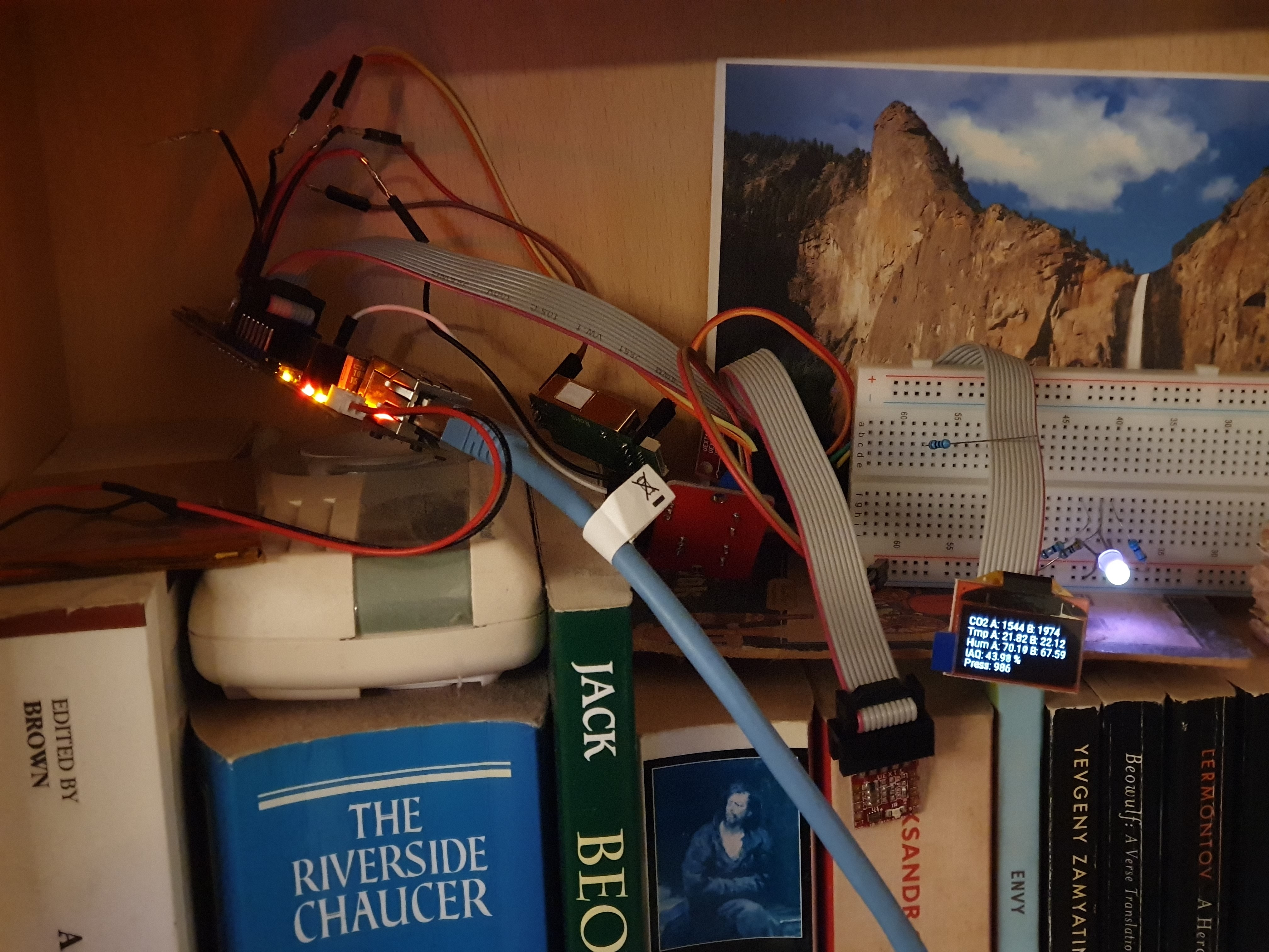
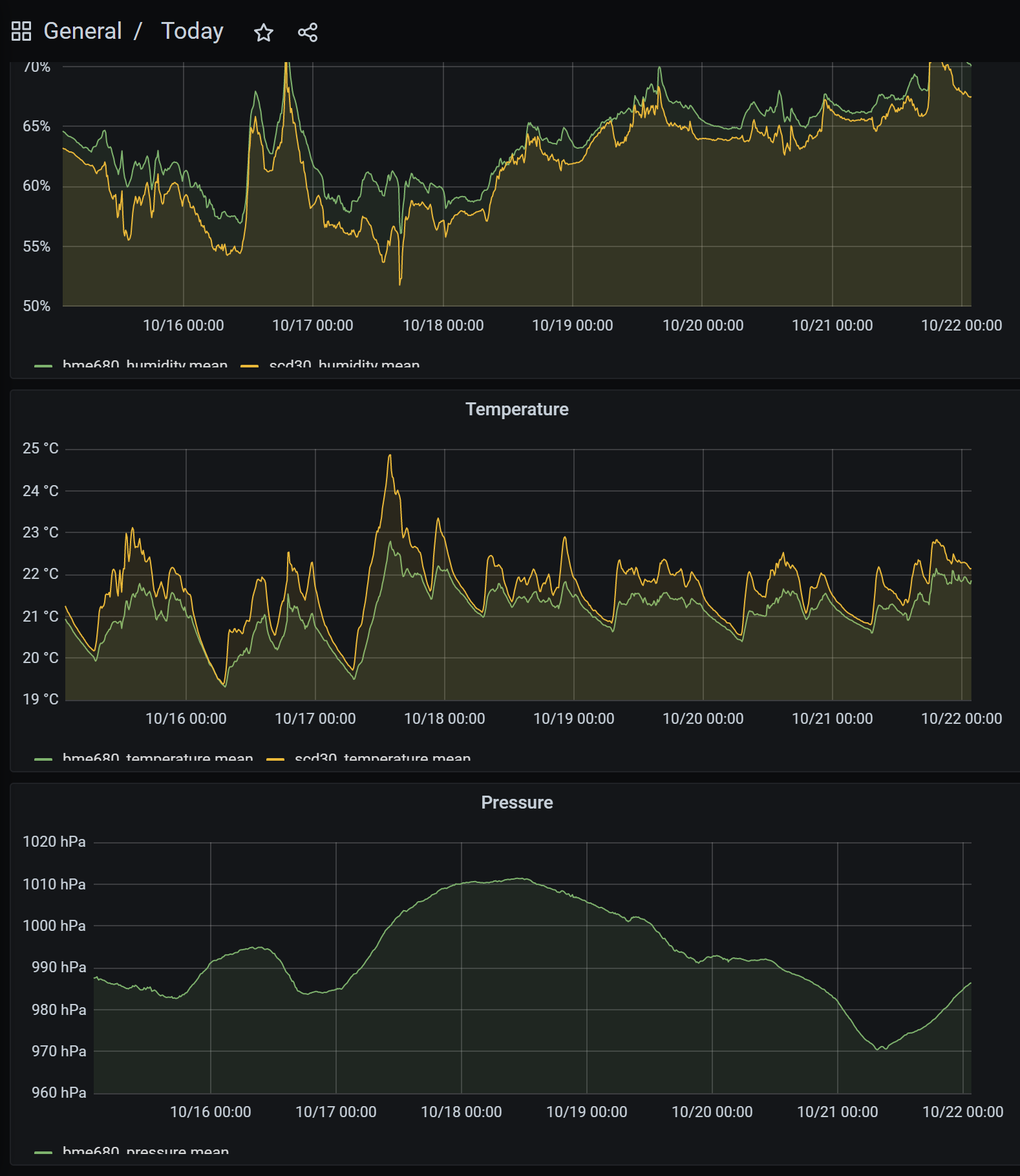
As you may be able to read from its little OLED display, it has three sensors, two are NDIR CO2 sensors and one is a IAQ + Humidity + Pressure sensor. Every few seconds the readings are posted by the board via REST to an Influx DB over the network, and it slowly pulses the LED from fully on to off by PWM. This has been running for a long time now on a ESPHome built firmware, it looks to me as reliable as the Devantech board. You may also note the lithium battery to the left, I have a 3000 mAh unit in there which I reckoned to be the best bang for the buck in terms of capacity to price ratio. Here is Grafana rendering the last week of InfluxDB records:
I guess my only real issue with this board is how hot its PoE DC to 5v circuit runs:
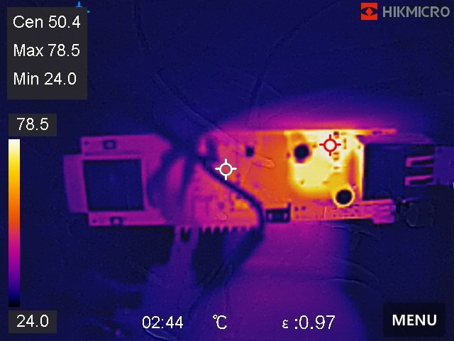
Yup, about 80 C. That’s well below the temperature rating of the components – especially the industrial grade ones which mine are – and in fairness this the eighth revision of the board is the least hot of any of the preceding revisions. Still, it kinda feels like wasted power consumption for no good reason other than reducing cost.
Thanks to this being an open source hardware design, I discovered that the DC-DC stepdown chip is the TX4138 whose datasheet can be found at https://datasheet.lcsc.com/lcsc/1811141153_XDS-TX4138_C329267.pdf. It claims an 84% efficiency. Assuming it’s a linear regulator taking the 5v to 3.3v and therefore burns as heat 33% of the current the ESP32 uses, a 100 mA draw by the ESP32 at 3.3v (one third of a watt) would be 133 mA of 5v, or two thirds of a watt. That turns into a minimum of 0.8 watts of PoE power, which is a best case efficiency of 41%.
Olimex seem to think it draws around a watt of PoE power if you don’t attach energy hungry peripherals, maybe 1.5 watts if the wifi is maxed out. I guess that therefore is +50 watts of constant background heating in my home.
BTW, one watt at €0.30 per kWh is €2.63 per year, so if the board costing €31 were ideally power efficient, it would take 9.1 years to pay back the added cost over the board I chose. I very much doubt that that the €31 board is more efficient however, it looks to me to also use linear converters. The WESP32 specifically mentions in its docs that when running off PoE it will get hot, and I couldn’t find any information on the heat output of the official Espressif dev board. In any case, high efficiency power conversion costs money, and the repay time is unlikely to be worth it for such low wattages.
ESPHome
In my Q3 2021 survey I spoke a lot about ecosystem depth and breadth greatly favouring the STM32 over the ESP32, after claiming I had done a lot of research. Unfortunately I somehow missed the elephant in the room which is the amazing and astonishingly capable ESPHome which I assume at the time I didn’t realise just how amazing it is. And, a game changer in fact, as it made me go all in on ESP32.
ESPHome comes across initially as a dumb microcontroller convenience firmware for Home Assistant, and I think because of that I dismissed it from further investigation at the time. That was a mistake, thankfully realised in time. ESPHome is in fact so capable that you don’t need Home Assistant at all, you can create firmwares which work with other ESPHome firmwares to solve a problem without any central server to coordinate things. That is a killer application for my use case. Furthermore, you can bulk orchestrate the upgrading of the firmwares of many devices chosen by category with zero effort over ethernet, which is another killer application for my use case. Finally, while ESPHome has a limited selection of hardware with direct support, apart from a few mildly painful omissions it does have support for a wide enough range of hardware that so long as you only buy peripherals it supports, it ‘just works’ with very little added effort.
Here is the ESPHome configuration file for the board above. You feed this to esphome run and it will compile an ESP32 firmware for you and automatically write it to the board over ethernet.
esphome:
name: esp32-poe
platform: ESP32
board: esp32-poe
on_boot:
- light.turn_on: led1
globals:
- id: brightness
type: float
initial_value: '1.0f'
- id: increment
type: float
initial_value: '0.01'
influxdb:
host: 192.168.x.x
database: HomeSensors
username: x
password: x
interval:
- interval: 100ms
then:
- light.turn_on:
id: led1
transition_length: 0ms
brightness: !lambda |-
if(id(brightness) <= .0f) {
id(brightness) = .0f;
id(increment) = -id(increment);
} else if(id(brightness) >= 1.0f) {
id(brightness) = 1.0f;
id(increment) = -id(increment);
}
id(brightness) += id(increment);
return id(brightness);
ethernet:
type: LAN8720
mdc_pin: GPIO23
mdio_pin: GPIO18
clk_mode: GPIO17_OUT
phy_addr: 0
power_pin: GPIO12
domain: .nedland
manual_ip:
static_ip: 192.168.x.x
gateway: 192.168.x.x
subnet: 255.255.255.0
use_address: 192.168.x.x
uart:
# Must use UART1 as UART0 is used by the logger!
rx_pin:
number: GPIO36
tx_pin:
number: GPIO4
baud_rate: 9600
id: uart1
debug:
i2c:
sda: SDA
scl: SCL
scan: true
frequency: 400kHz
#spi:
# clk_pin: GPIO14
# mosi_pin: MOSI
# miso_pin: MISO
binary_sensor:
- platform: gpio
pin:
number: BUTTON
inverted: true
name: "Button 1"
# LED
output:
- platform: ledc
pin: GPIO33
id: gpio_33
frequency: "14648Hz" # 80 Mhz clock so 4096 steps
light:
- platform: monochromatic
output: gpio_33
id: led1
name: "LED"
# CO2 sensor
# Temperature, pressure, humidity sensor
bme680_bsec:
address: 0x77
sensor:
- platform: adc
pin: GPIO35
name: "Battery voltage"
- platform: adc
pin: GPIO39
name: "External voltage"
- platform: mhz19
co2:
name: "MH-Z19 CO2 Value"
id: co_1
temperature:
name: "MH-Z19 Temperature"
update_interval: 30s
uart_id: uart1
automatic_baseline_calibration: true
- platform: scd30
co2:
name: "SCD30 CO2 Value"
id: co_2
temperature:
name: "SCD30 Temperature"
id: temp_2
humidity:
name: "SCD30 Humidity"
id: hum_2
update_interval: 30s
address: 0x61
automatic_self_calibration: true
# - platform: bme680
# i2c_id: i2c0
# temperature:
# name: "BME680 Temperature"
# oversampling: 16x
# pressure:
# name: "BME680 Pressure"
# humidity:
# name: "BME680 Humidity"
# gas_resistance:
# name: "BME680 Gas Resistance"
# address: 0x77
# update_interval: 5s
- platform: bme680_bsec
temperature:
name: "BME680 Temperature"
id: temp_1
pressure:
name: "BME680 Pressure"
id: press_1
#on_update:
# write scd30.ambient_pressure_compensation
humidity:
name: "BME680 Humidity"
id: hum_1
iaq:
name: "BME680 IAQ"
id: iaq_1
co2_equivalent:
name: "BME680 CO2 Equivalent"
breath_voc_equivalent:
name: "BME680 Breath VOC Equivalent"
# - platform: ltr390
# uv:
# name: "LTR390 UV Index"
# light:
# name: "LTR390 Light"
# address: 0x23
font:
- file: "gfonts://Roboto"
id: roboto
size: 12
display:
- platform: ssd1306_i2c
model: "SSD1306 128x64"
rotation: 180
lambda: |-
it.fill(Color::BLACK);
it.printf(0, 0, id(roboto), Color(255,255,255), TextAlign::TOP_LEFT, "CO2 A: %.0f B: %.0f", id(co_1).state, id(co_2).state);
it.printf(0, 13, id(roboto), Color(255,255,255), TextAlign::TOP_LEFT, "Tmp A: %.2f B: %.2f", id(temp_1).state, id(temp_2).state);
it.printf(0, 26, id(roboto), Color(255,255,255), TextAlign::TOP_LEFT, "Hum A: %.2f B: %.2f", id(hum_1).state, id(hum_2).state);
it.printf(0, 39, id(roboto), Color(255,255,255), TextAlign::TOP_LEFT, "IAQ: %.2f %%", (id(iaq_1).state/5.0f));
it.printf(0, 51, id(roboto), Color(255,255,255), TextAlign::TOP_LEFT, "Press: %.0f", id(press_1).state);
# Enable logging
#logger:
# level: VERBOSE
# level: VERY_VERBOSE
# Enable Home Assistant API
api:
password: "xxxx"
reboot_timeout: 0s
ota:
password: "xxxx"
# Enable webserver
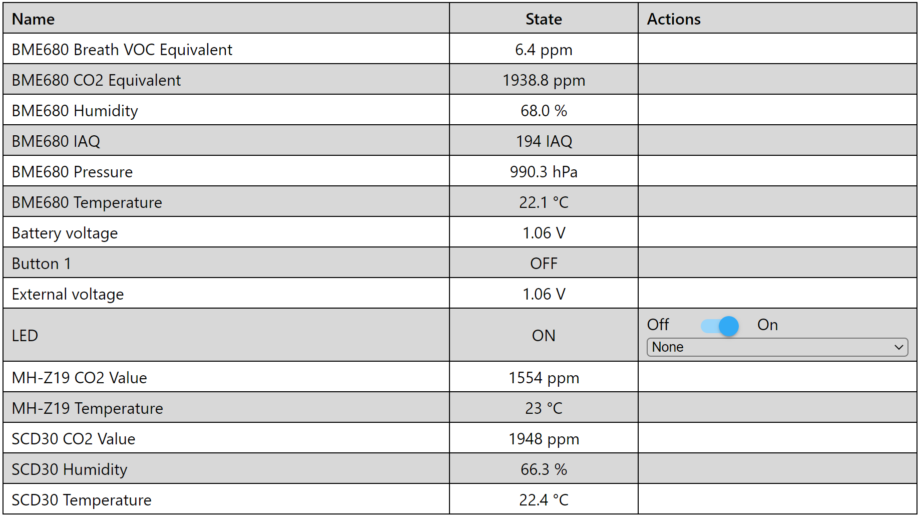
web_server:
port: 80
As you can see, it’s basically YAML describing the board and what is connected to it and where. Rather usefully it autogenerates a live web page on a web server served by the board, just like the one I made for the Devantech board:
I haven’t really exercised the support for writing out complex logic much yet – you can easily do stuff such as ‘if humidity exceeds 80%, switch relay on’ – but I shall be doing so when I set up my 12v battery installation. I have bought a small 20w solar panel and a cheap low end 12v solar charger which isn’t very clever, so I will also be adding one of these PoE boards with a lithium battery and an added high quality time and date peripheral over I2C. It will calculate sunrise and sunset from the current date, and physically disconnect the solar charger from the battery during night times to prevent it sucking power out of the battery. I then will have various things hanging off the 12v battery, specifically 24v LED strip lighting and an alarm system so if anybody tries to rob me, I can light the place up and set off loud sirens, and it’ll be completely independent of mains power so even if they disconnect or cut the power lines going into the container, it won’t help them.
Once I have the security system in place I can start filling the shipping container with expensive stuff, currently I can’t take the expensive stuff out there as I can’t risk it – even though the shipping container has a CEN class 4 lock on it (the highest CEN grade is 6, and those locks cost half a grand or more each), and it would take a cutting torch to get in there, the easiest way to rob it is simply to steal the whole container and I have no protection against that until I get my battery powered alarm system installed.
| Go to previous entry | Go to next entry | Go back to the archive index | Go back to the latest entries |