Word count: 3239. Estimated reading time: 16 minutes.
- Summary:
- The Naber Thermobox non-return valve has been tested and found to have a u-value of 0.775 W/m²K or lower, making it a suitable solution for extracting cooking fumes in a certified Passive House without compromising its thermal integrity. The five-chambered unit is expected to have an air leakage rate of around 5 m³/hr at 50 Pa, meeting the requirements for airtightness.
Wednesday 6 August 2025: 10:30.
- Summary:
- The Naber Thermobox non-return valve has been tested and found to have a u-value of 0.775 W/m²K or lower, making it a suitable solution for extracting cooking fumes in a certified Passive House without compromising its thermal integrity. The five-chambered unit is expected to have an air leakage rate of around 5 m³/hr at 50 Pa, meeting the requirements for airtightness.
- Lose weight
- On this I have been spectacularly unsuccessful, I have actually slightly
gained weight
 .
.
- On this I have been spectacularly unsuccessful, I have actually slightly
gained weight
- Do stuff with the kids I couldn’t normally do
- On this I have been very successful, they are quite sick of how much time they have been spending with me! Over 250 km with the kids on the back of the Fiido T2 Longtail and counting!
- Move ISO standards committees
- Four major paper proposals written for the WG14 meeting in August, and I am all set for the trip and meeting. I wish I had written more papers, but I think four big papers is still pretty good.
- Clear project backlogs
- I have done absolutely nothing on the 3D services layout. I now expect I’ll have to force myself to do those as if a day job after the kids go back to school. I have cleared all but one of the house build solutions testings however, so I’m going to call this a partial success.
I guess that’s an overall score of about two thirds successful? I am a bit annoyed about the lack of weight loss as I’ve been starving myself. But as mentioned last post, those trips abroad with all the nice food and all the beer from it being an unusually nice summer for Ireland I think has more than made up for calories. I expect to go completely tee total as I usually do after Megan’s birthday until Christmas, so maybe the weight will fall off then?
Regarding new employment, I haven’t been trying to find new work, but I have been watching ever more people I’ve known for years also enter the jobs market. Lots of very senior, very talented, developers. I haven’t seen it this bad in tech since the 2009 recession. If it keeps going like this, it’s going to be as bad as the 2001 recession which was especially hard on the tech industry. Anyway I’ll worry about all that next month.
This post will be about testing my solution to a long standing problem in certified Passive Houses: kitchen cooking fumes extraction.
The problem
Certified Passive House for my climate zone requires the total outer fabric u-value to be under 0.20 W/m2K or so (i.e. all windows, walls, roof, floor etc when all put together the total thermal transmittance must be below 0.2 watts per square meter per degree of temperature difference). Additionally, airtightness must be better than 0.6 indoor air changes per hour. For both these reasons, kitchen cooking fumes extraction to the outside is problematic:
Most kitchen extractor vents have a u-value around 25 W/m2K – though this is a 150 or 125 mm diameter region, so it won’t impact the building fabric average by much. Where you get more trouble is from the thermal bridging as you effectively have a hole to the outside – this causes condensation and mould unless you put perhaps 50 mm of insulation around the duct. All that insulation is unwieldy, especially if trying to route it in a kitchen e.g. behind cabinets.
Kitchen extractor vents should have a non-return valve to prevent outdoor wind blowing air into the kitchen through the extractor, which if not prevented would fill your house with lovely stale cooking smells as well as cold air. Most of these non-return valves don’t really close properly, you’ll often hear them banging with wind gusts outside. This means they ruin the excellent air tightness of your Passive House.
For these reasons the Passive House Institute recommends recirculating cooker hoods. These pass the fumes through a filter before releasing them back into the home. I’ve never been keen on these – from my own testing I have found the thin insubstantial and cheap filters typically fitted to cooker hoods saturate within a few weeks. And nobody is going to be changing these filters every few weeks in practice. If you’re going to do this right, you should fit commercial kitchen grade fume filtration which does actually work. Expect to spend thousands on such an installation, and it is noisy and uses lots of electricity to run.
The Naber Thermobox non-return valve
That made me wonder if a decent thermally broken extractor non-return valve could be possible? I had found the Naber Thermobox which is an affordable, thermally broken unit costing €48 inc VAT at the time of writing. It consists of three ABS plastic non-return valves with two 20 mm thick pockets of trapped air between them. Naber claim that this unit has a u-value of 2.2 W/m2K. They also claim that it will only open with 65 Pa of air pressure, which is implemented using two small magnets per flap to ensure that the flap is either completely closed or completely open – it cannot be slightly open, or get flapped open and closed by wind gusts. Theoretically, you could even do the air tightness blower door test without these covered because the air tightness test runs at 50 Pa, so it won’t open the Naber unit. It’s probably easier to show you a video of it than describe it in words:
The Naber Thermobox insulated non-return valve
This looks promising, though I note from inspection that it isn’t particularly air tight – the plastic flaps do have slight gaps around them as they need to permit some air to pass in order to whip them open when the extractor fan turns on.
There is something else cool about Naber’s design: each layer in these units simply snaps together. This lets you amalgamate them easily like this:
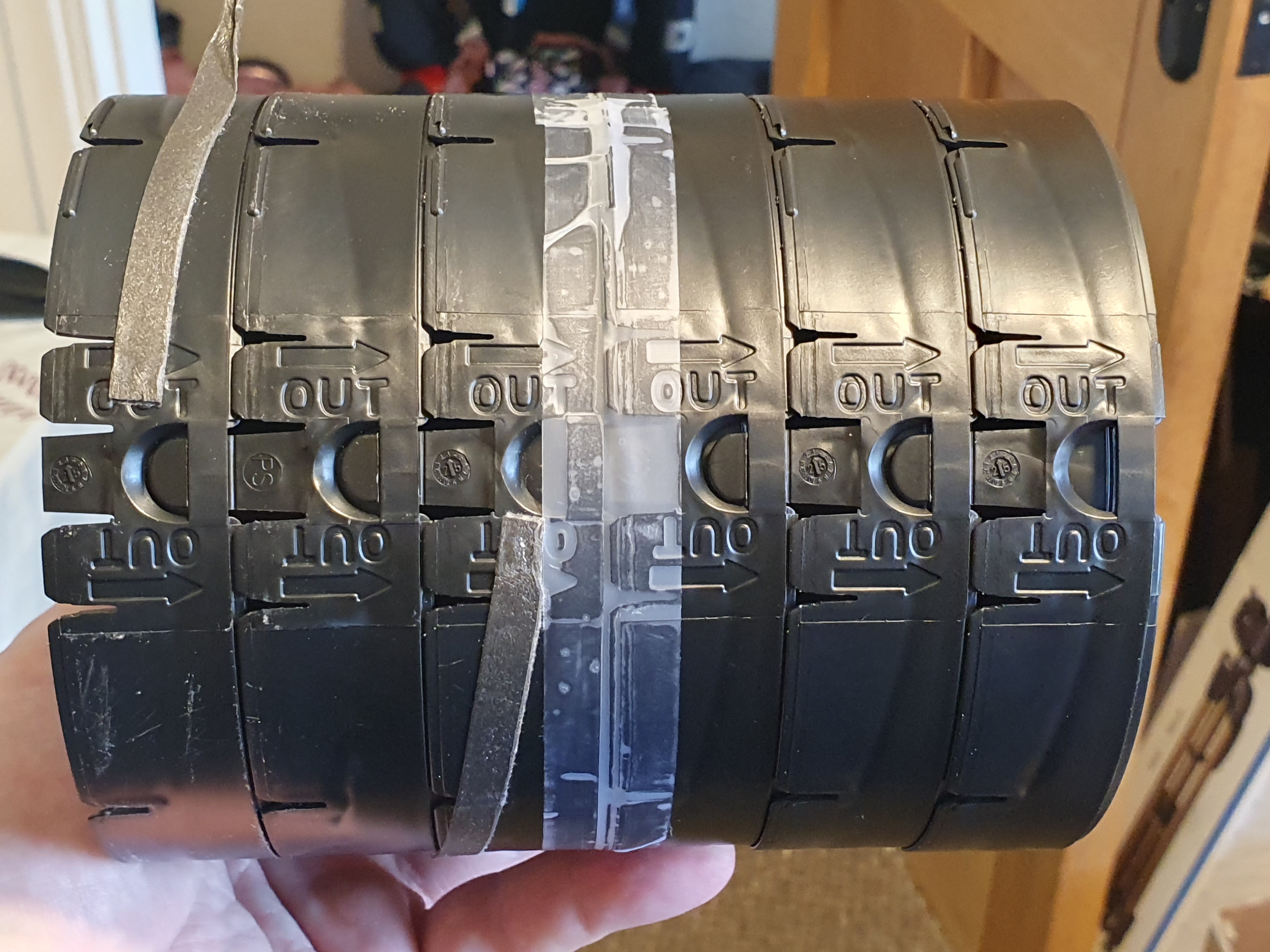
And now I have a five chambered insulated non-return valve which ought to be significantly better than a two chambered edition both thermally, and for air tightness.
Thermally broken kitchen extractor testing rig
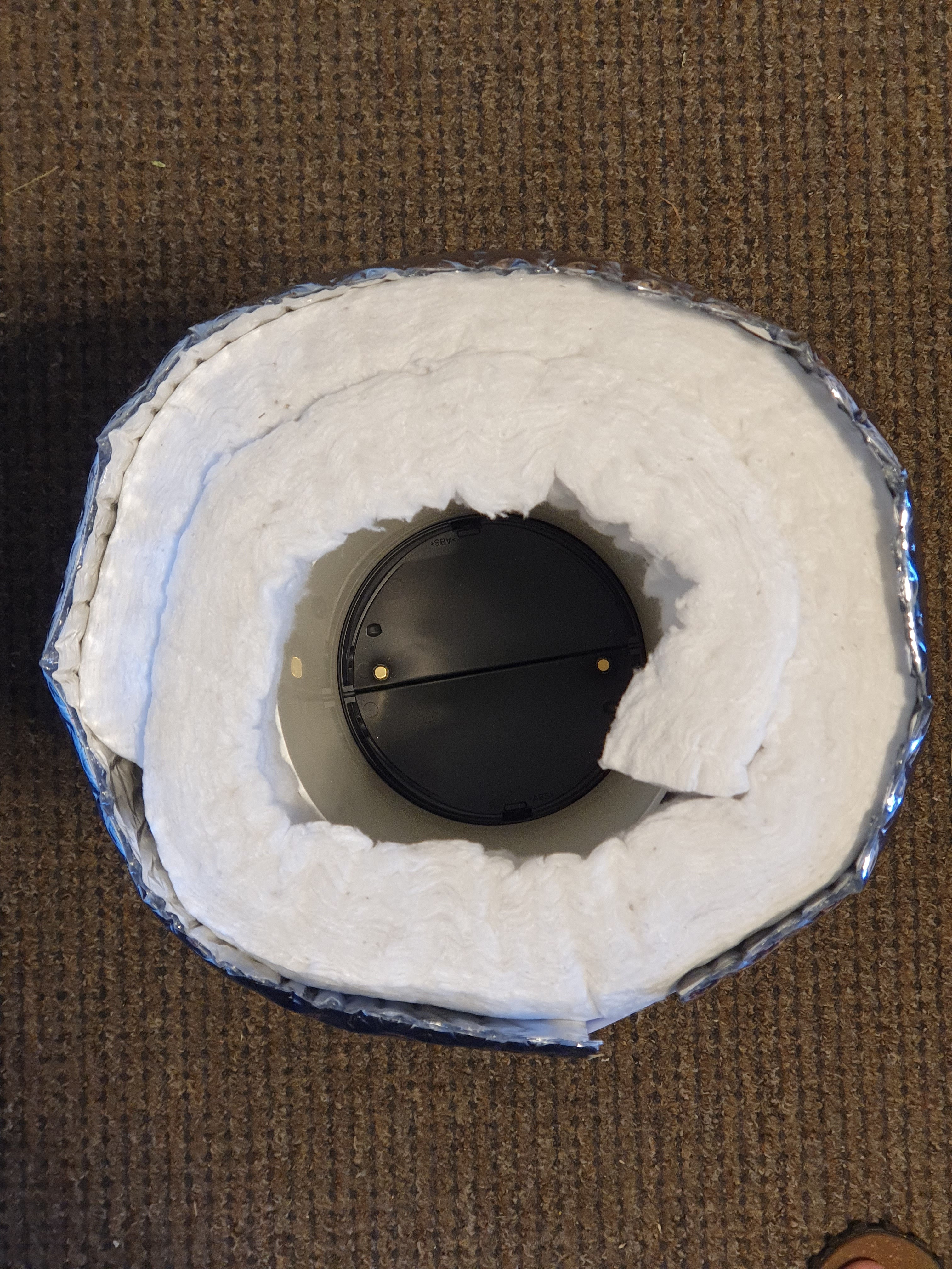
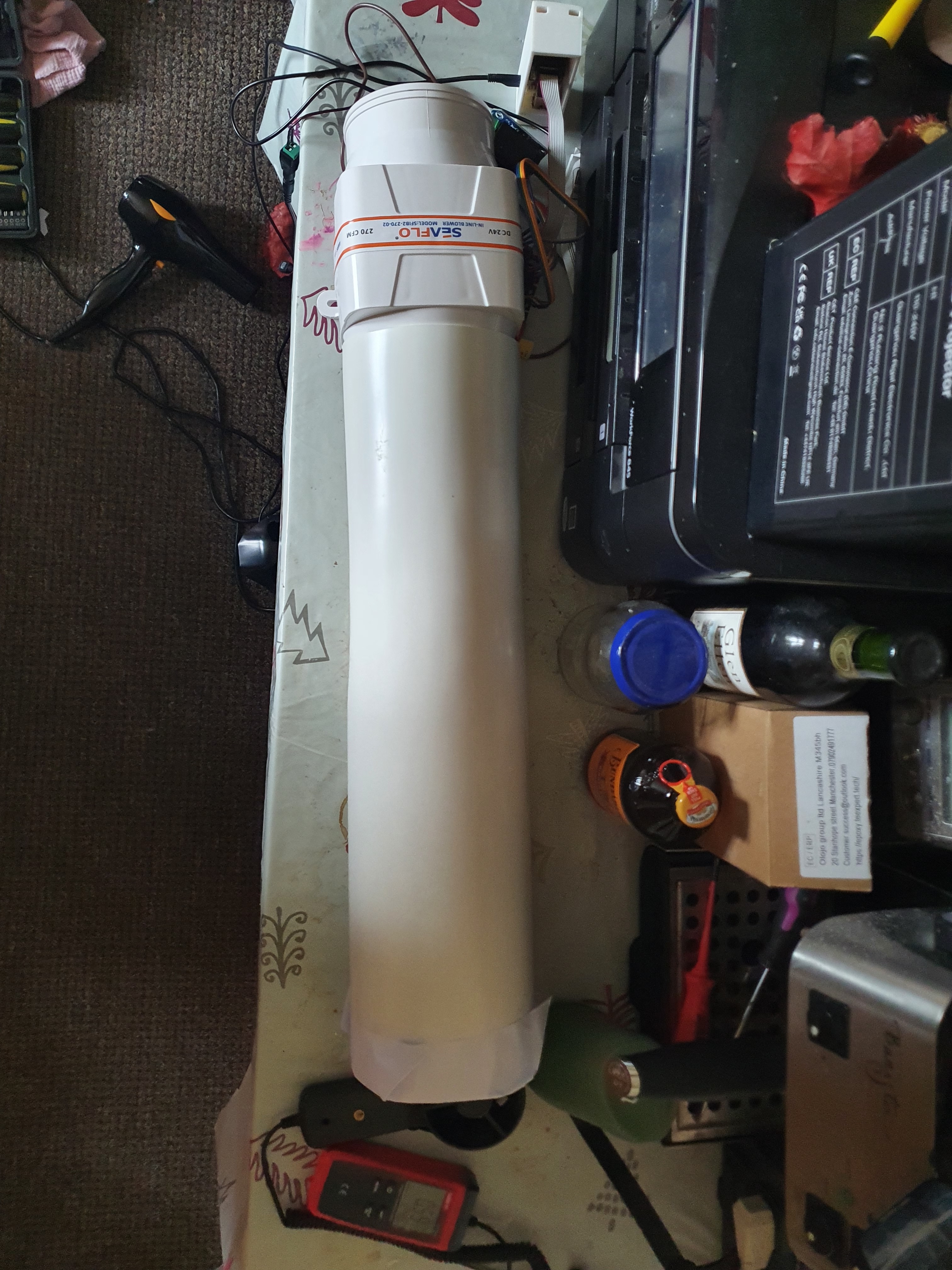
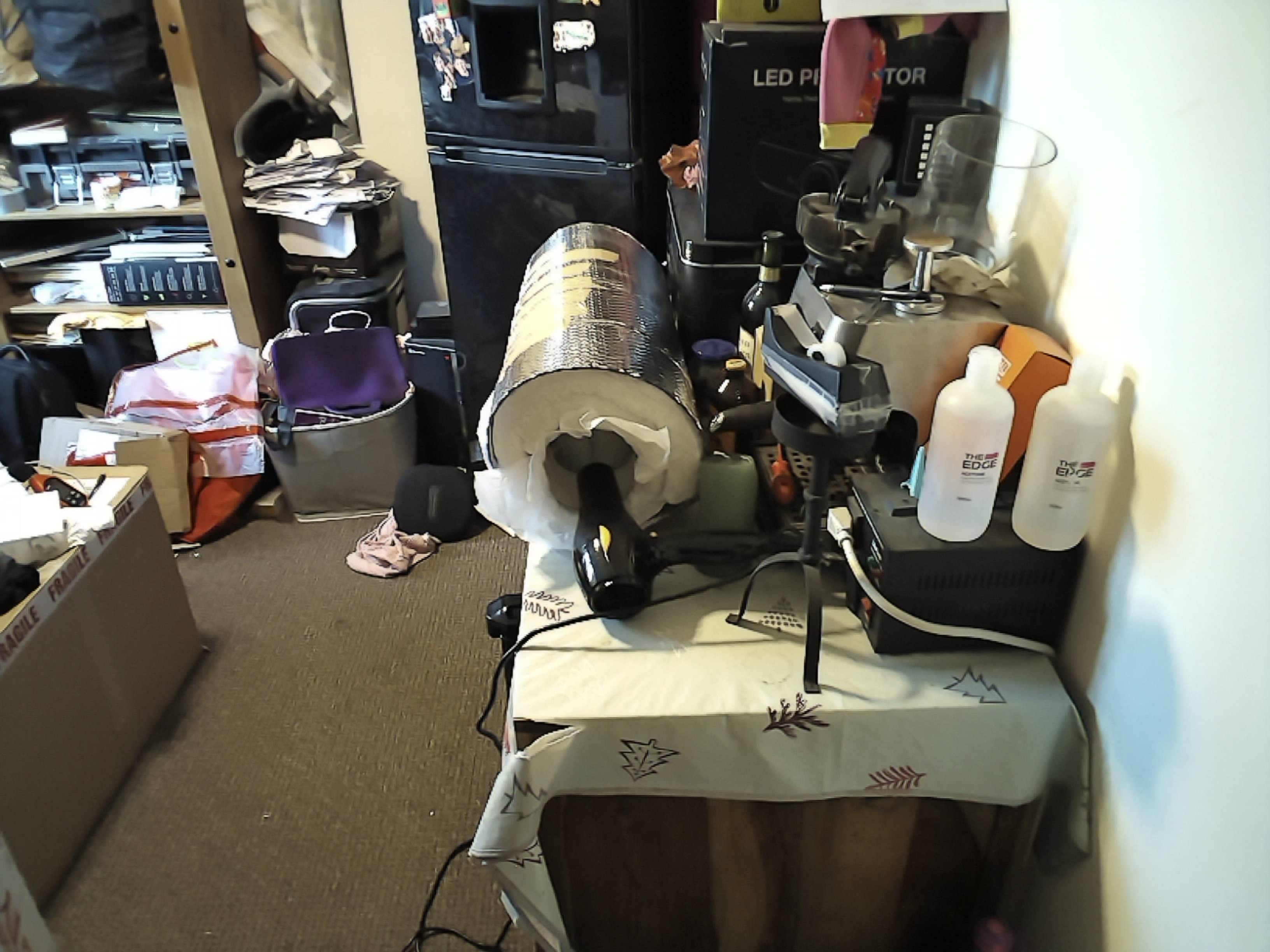
I purchased from an online German vendor a bunch of Naber ventilation kit (enough to test if my planned duct routing under the kitchen cabinets would work – I now know it will). One of the items was a 125 mm diameter half metre long PVC pipe suitable for penetrating the wall of the house (which is 0.5 metres thick if excluding the interior service cavity). To mimic the cellulose insulation which would surround it, I fitted a roll of 40 mm thick Aluminium Silicate Ceramic Fibre blanket which I got off Amazon at €66 inc VAT per sqm (which is about 0.1 W/mK thermal conductivity which isn’t great, however its singular advantage is it is happy well past 1000 C so it’s the right stuff to use for chimney flues etc). Because the fibre blanket is itchy, I then wrapped that in Aluminium foil covered bubble wrap which is good at reflecting heat:
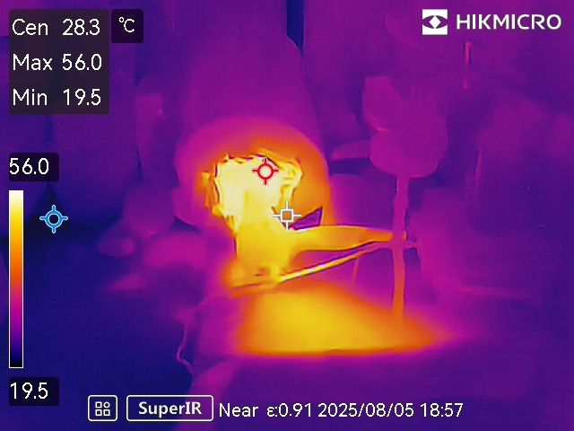
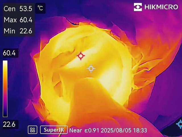
I then stuck Megan’s hair dryer in one end, and used my thermal camera to measure what heat was going in and what transmitted through. Unfortunately on my first attempt I didn’t realise just how hot her hair dryer gets when blowing into a highly insulated tight space and I melted my first Thermobox unit which was fifty euro wasted:
Luckily I had another two of those units for testing and the PVC duct while it warped from the heat it was sufficient for further testing. I used the lowest heat setting after this!
Initial testing revealed an issue: the hair dryer blows with considerable air pressure, and I suspected some of the heat was being unreasonably blown through the unit. So I came up with a ‘sock’ made out of greaseproof paper:
The reason I couldn’t use tinfoil is because it reflects infrared and therefore makes the thermal camera useless. The greaseproof paper is meant to be used in ovens, and it worked a treat: the hair dryer blew into the greaseproof paper sock, it heated up to 65 C or so. That was against the front of the non-return value, so some of the heat shined onto the unit under test plus the air around heated up. That then heated the first layer of ABS plastic of the unit, which then shines heat onto the air pocket and the next plastic layer behind it. As the heat cannot escape outside the sides due to the thick insulation, and the hair dryer side reaches a steady state of hot quickly enough, you can then measure how long it takes for how much heat to pass through the unit. From that, one can theoretically calculate what the thermal conductivity of the unit is.
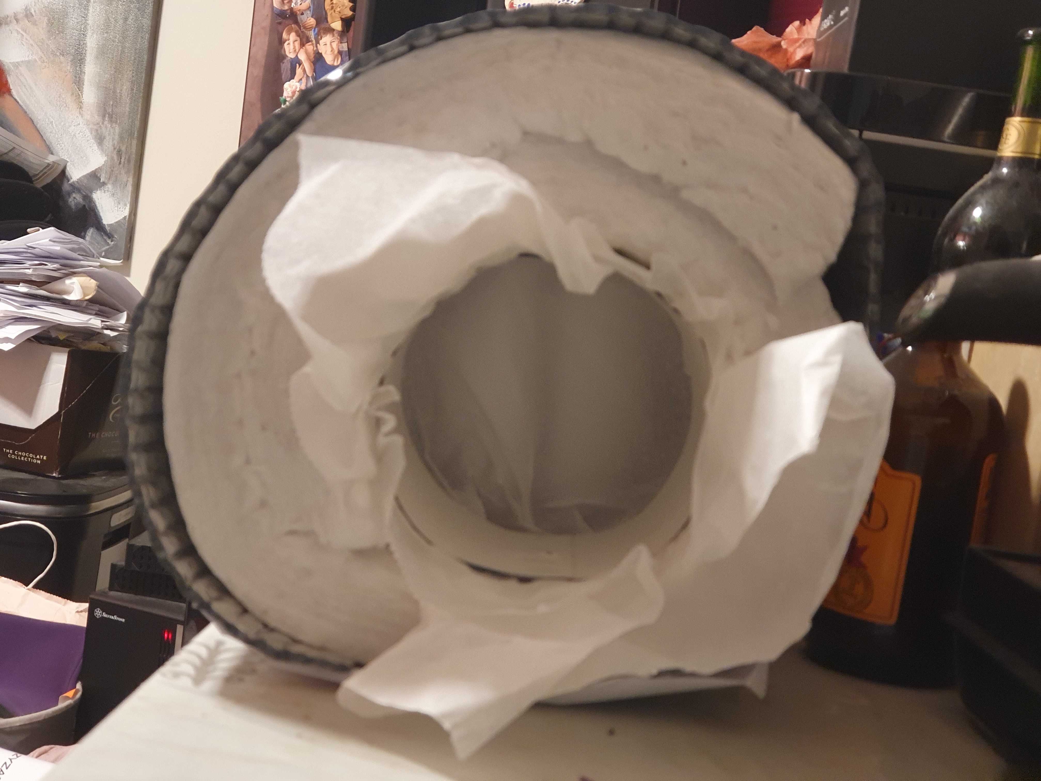
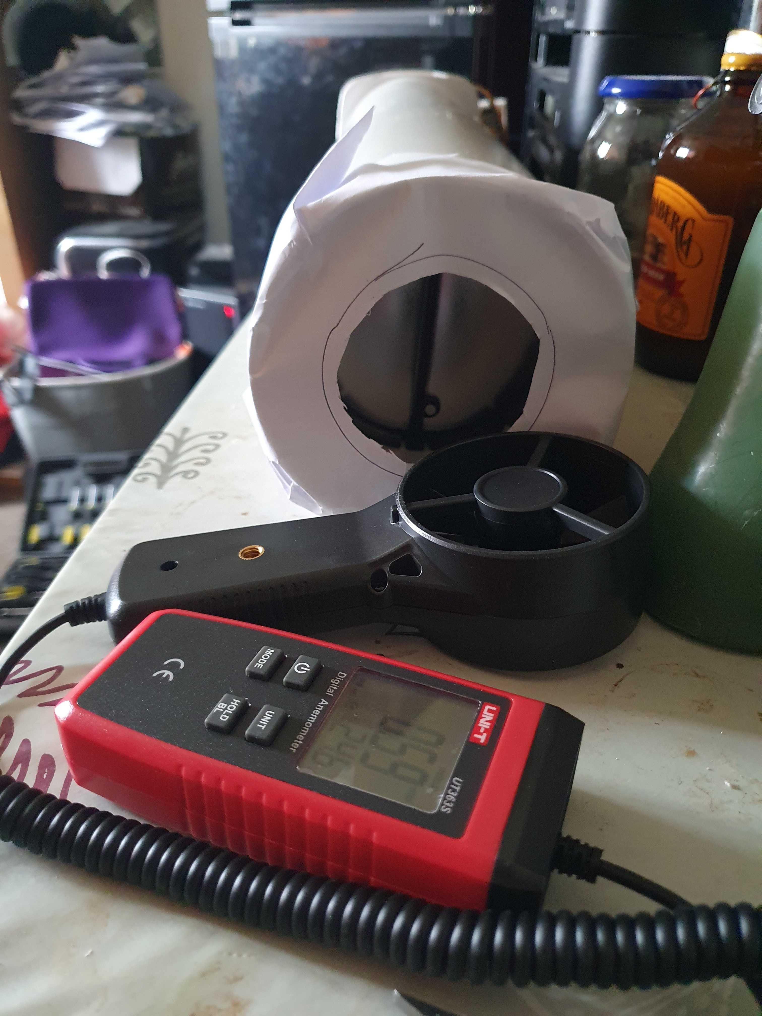
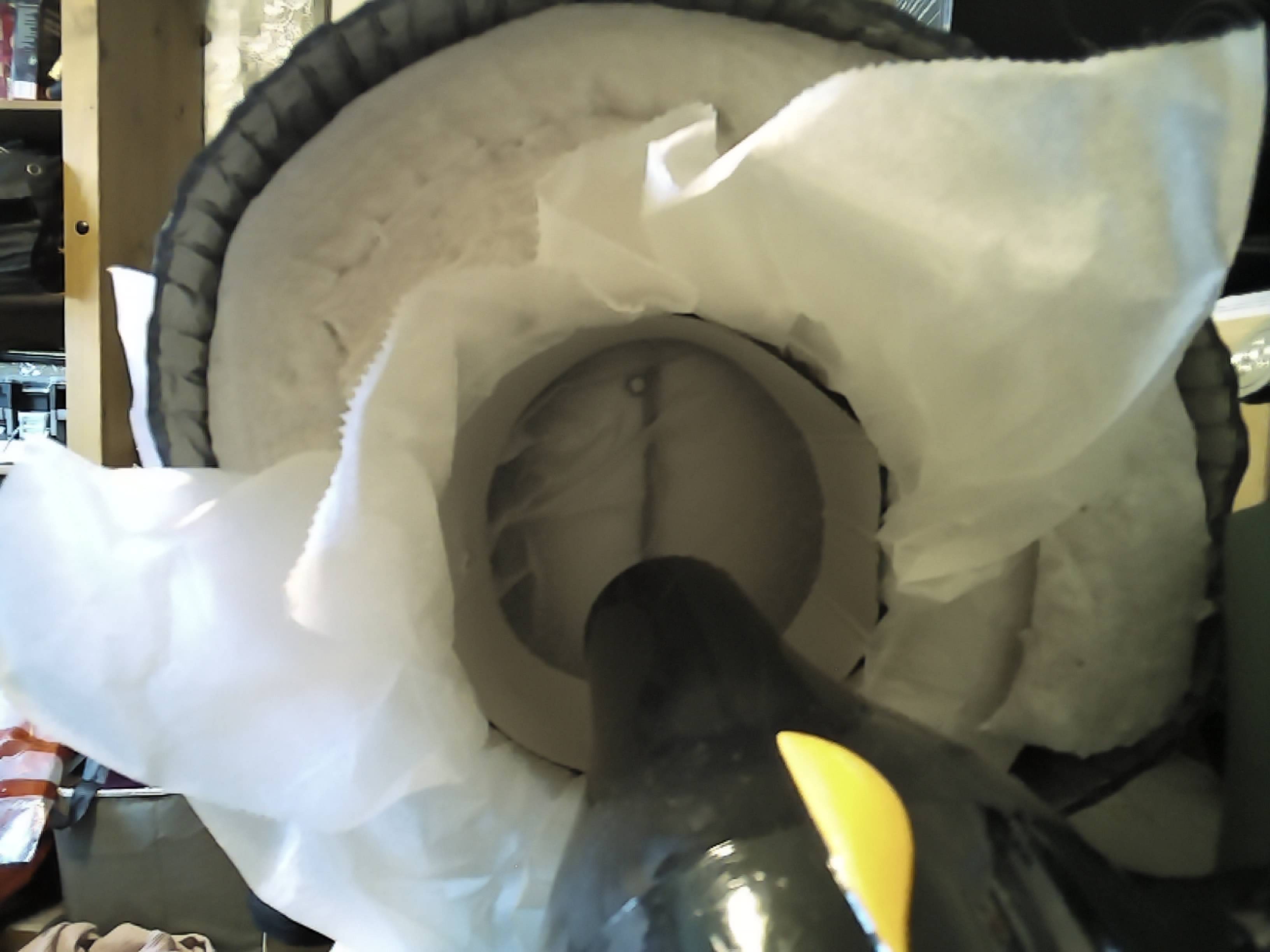
The other part of the testing is for air tightness. For this I put one of the bilge fans in one end snug and for the other end I made a paper hole to focus all the airflow into the right size for my anemometer to measure, as the little air getting through the unit was just on the cusp of not being readable:
Thermal testing
I did two runs – I should have done more, but they are incredibly boring and tedious to do. They involve taking a photo with the thermal camera every minute. For the single unit (two air compartments) case, it wasn’t too bad: it took about fifteen minutes for the cold end to reach 25 C having started from 20.6 C. The reason I chose 25 C as the test end point is because the temperature increase (4.4 C) is approximately 10% of the hot to cold end differential (44 C), and if the cold end gets much warmer than the surrounding air then convection will carry off heat which affects the measurements.

The thermal camera does get a bit of noise at the sub degree level, but the trend is clear over time – the cold end gets warmer.
For the double unit (five air compartments) case, the testing was very considerably more tedious:

Yup, that is a full ninety minutes of testing to reach 25 C. Very, very boring to do, but I did catch up on all my internet reading I suppose. Here is a sped up time lapse of the thermal photos:
Ninety minutes of thermal photos in under one minute!
I reckon it took a good forty minutes before any heating around the top of the non-return valve becomes obvious in that video.
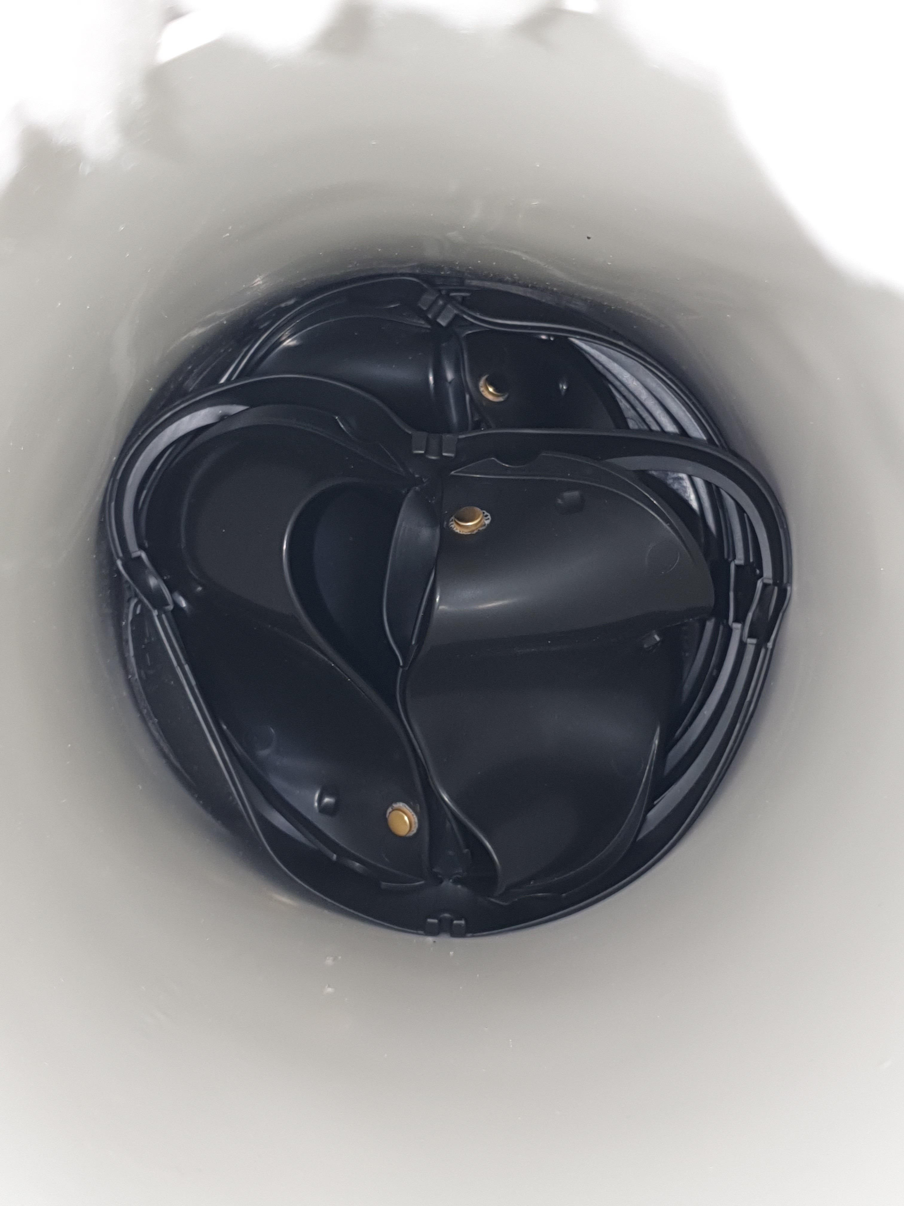
Straight off from that alone one can deduce that the five compartment return valve is five times more insulating than the two compartment return valve. In case you’re wondering if six non-return valves open easily when the extractor fan starts up:
If you look carefully at the design, each of the plastic flaps has a little ‘foot’ on its back designed to smack into the next layer of flap behind it. So when the front flaps open, they smack into the next layer which knocks them off their magnetic closed state i.e. opening cascades. Sellotaping two units together doesn’t affect this – each of the five layers of non return value behind the front layer open in turn.
Finally, some pictures of the hot end to round out this section:
Air tightness testing
I already showed you how I did the test above, and you could even make out a measurement. The bilge fan, which is a 24v model, but I ran it at 12v which pushes 9 m/s of air if left free:
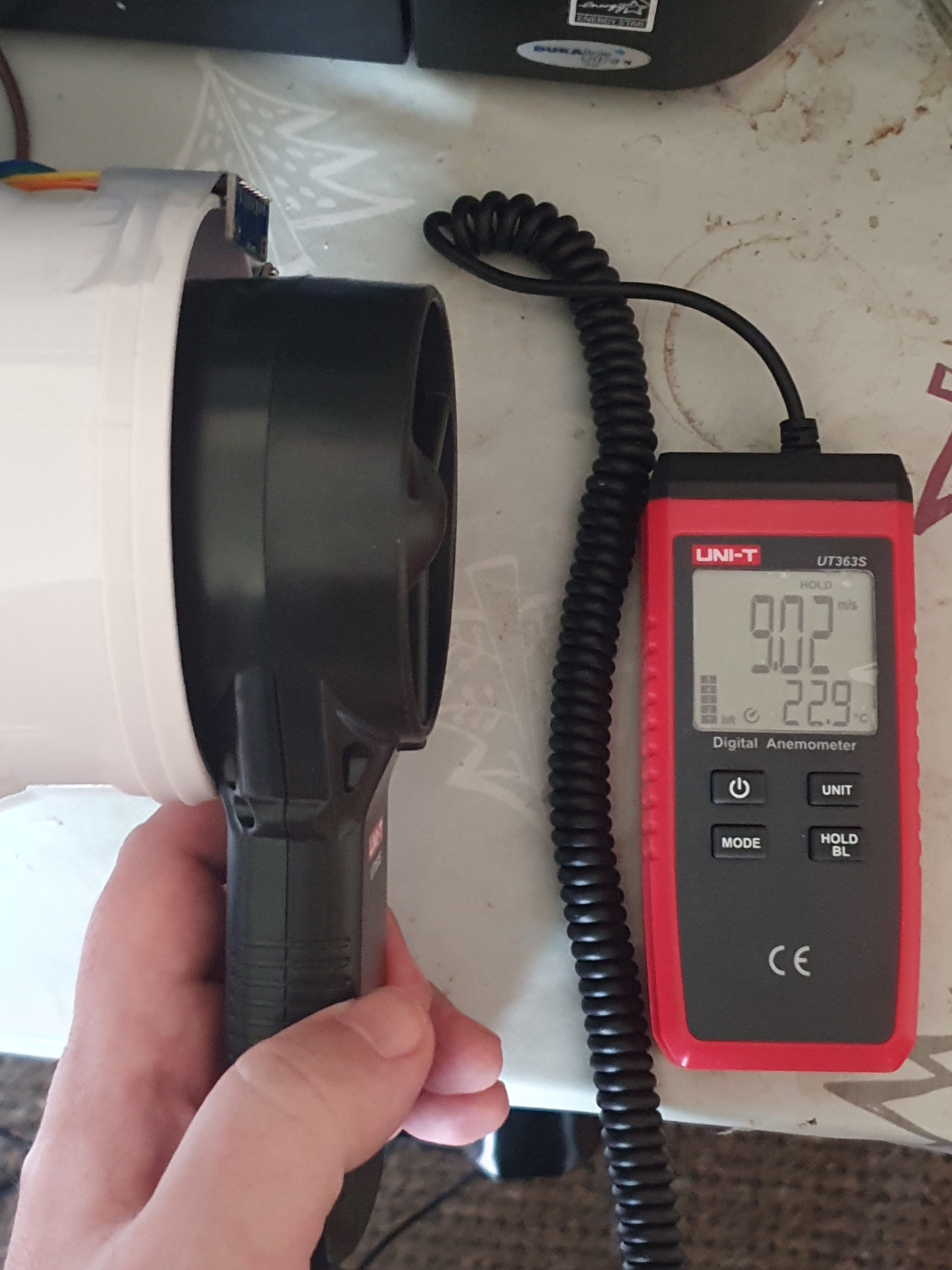
If the fan is tightly inserted into one end of the pipe with the five air compartments non-return valve inside, I measure 0.6 m/s of air getting through a hole with diameter 65 mm:
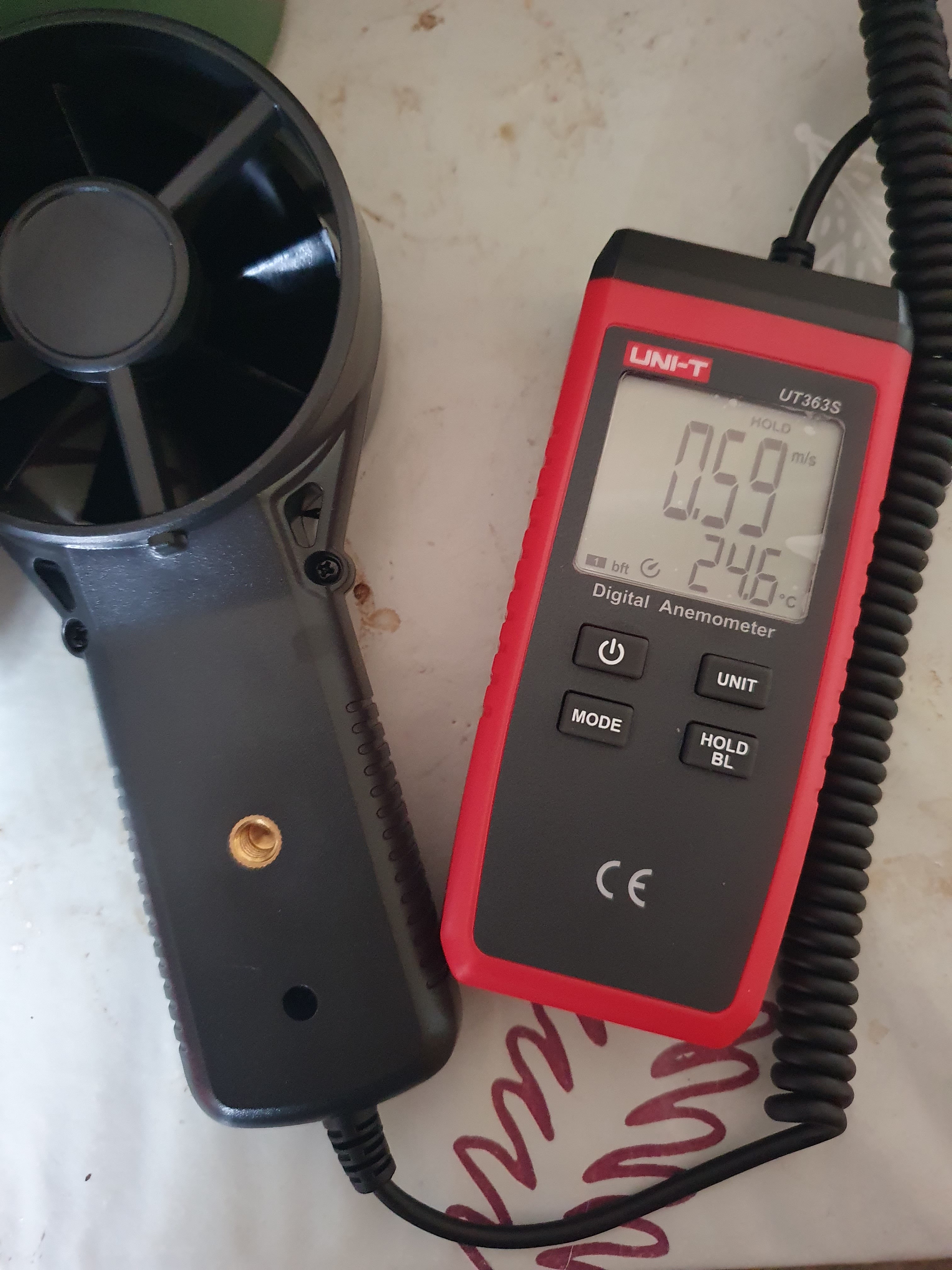
Which is 0.002 m3 of air per second, or 7.168 m3 of air per hour. There will be 806 m3 of air in the house, this means we can leak no more than 483 m3 of air per hour at 50 Pa. This would mean that the five compartment unit should be well within Passive House air leakage, but things do depend on what static pressure is being generated by the fan outside the unit.
If when left free the bilge fan it moves 9 m/sec of air through a 100 mm diameter pipe, that is 254 m3/hr (it does about 450 m3/hr if running off 24v, so this seems about right – air flow is proportional to fan speed, so you get ~56% of max air flow on 12v instead of 24v). The manufacturer of the Seaflo fan doesn’t provide static pressure ratings (and it is hard for me to measure those until I get the differential pressure sensors up and working), but I did find a review on US Amazon where the guy reckons 0.89 inches of static pressure, which is 225 Pa. Static pressure is negatively related to air flow squared, so halving pressure only reduces air flow by one quarter. Therefore, if the fan is turning at 56% of full speed, you would expect static pressure to drop to 70 Pa.
Therefore, as a rough guesstimate, that 7.168 m3/hr at 70 Pa would be 5.55 m3/hr at 50 Pa. This would be 1.1% of the maximum air leakage allowed, which seems acceptable, even though in my specific case I’ll actually have two of these ducts – one for extraction, one for make up air to more rapidly purge the kitchen of smoke. Even then, both those ducts should contribute no more than 2.5% to whole house air leakage.
More (but harder) maths …
We have a probable air tightness measurement for the doubled up Naber Thermobox non-return valve, but can we calculate a thermal conductivity?
The formula for the rate of heat flow is:
We know the area of the unit to be 0.01227 m2 as it has a 125 mm diameter. For the two compartment test, it is 0.055 m long and the temperature difference was 44 C. Rearranging:
Simplifying:
The two compartment unit claims a u-value of 2.2 W/m2K and therefore one would expect a ~1.2 watt heat flow, which feels plausible. Let’s see if we also saw that during testing …
The thermal camera measures the surface of the final ABS plastic flap, so if ABS plastic has a heat capacity of 1500 J/kgK, a density of 1115 kg/m3, and the flaps in our case are 1 mm thick, I reckon it would require 1673 joules to raise a 1 m2 sheet one millimetre thick by one degree celsius. Or, put another way, if one applied 1673 watts to that sheet, its temperature would rise by 1C per second. For our much smaller sheet, that becomes 20.52 joules per degree.
We know it took 780 seconds for our final flap to rise by 4 degrees, therefore that was 195 seconds per degree, or 0.005128 degrees per second. This implies a heat flow of 0.11 watts, which means our testing is about a factor of ten better than the manufacturer claimed value.
Losses to convection to outside air are maybe 0.06 watts per degree above ambient air which isn’t enough to remotely close the gap.
Let’s now look at the five chambered unit: firstly, if a two chambered unit 0.055 m long has a u-value of 2.2 W/m2K, that would imply a five chambered unit 0.125 m long would have a u-value upper bound of 0.986 W/m2K. However, most of the insulation will come from the air (0.026 W/mK) versus the ABS plastic flaps (0.1 W/mK) and we have 2.5 times the number of air chambers. So I would suggest a u-value lower bound of 0.775 W/m2K. With a 37 C temperature difference, that is a heat flow between 0.352 watts and 0.448 watts which is 3.4 times better and 2.7 times better than the two chamber unit respectively. This is still rather lower than expected given my second test took five times longer than my first test, but let’s keep going by stating the heat flow equation for our second test:
Simplifying:
This time it took 5160 seconds for our final flap to rise by 2.6 degrees, therefore 0.0005039 degrees per second. This implies a heat flow of 0.01 watts, which is even more confusing because this test took five times longer than the first test, not ten times longer. It also implies a test unit u-value of 0.022 W/m2K which is plainly ridiculous.
I think I must surely have either a mistake in my maths or I made some mistake during testing. Quite frustrating after all the effort invested!
Conclusion
I suppose at least I discovered that the Naber Thermobox is not worse than manufacturer claims for thermal conductivity, and I probably did determine a reasonably accurate figure for air tightness which is useful, as the manufacturer said nothing about that aspect of the unit.
Obviously it’ll be the five chambered unit that I’ll be fitting. It should have a u-value a good bit below 1 W/m2K and an air leakage rate of around 5 m3/hr at 50 Pa. Those should enable reduced thickness insulation around the ducts, which will make routing these ducts underneath and behind the kitchen cabinets tractable, as I can only really allow for 25 mm of insulation – 50 mm just won’t fit.
Theoretically speaking, the non return valve should be installed close to the outside of the building to minimise thermal bridging. However there is a superior alternative – one could fit one half on the outside, and the other half maybe about half way through the wall. This increases the thickness of the pocket of air trapped between the two, improving insulation. I reckon it could improve the total assembly u-value by around 10%. What I don’t know is whether the flaps would whip open as well, as when they are together the little feet create a cascade open and I can see that a second nearly airtight seal behind the first could create a lack of pressure shock to whip open the second unit.
Thankfully, these Naber units are easy to install and remove – you just twist them in and out of place. So I can experiment once the house is built. It also means if they ever get clogged with grease, or the plastic gets worn down, or anything else goes wrong with them, they are dead easy to remove and repair or replace.
All in all I think I’m very happy with this affordable solution to extracting cooking fumes without ruining passive house.
What’s next?
Obviously differential pressure sensor testing is the next big task, and as we’re handily getting through August it’s beginning to feel urgent. I’ll endeavour to get it done by the end of this weekend, though it may be a few days into next week for me to write everything up.
| Go to previous entry | Go to next entry | Go back to the archive index | Go back to the latest entries |