Word count: 2118. Estimated reading time: 10 minutes.
- Summary:
- The Devantech dS3484 ethernet relay and input board was used to control a 24v AC power supply and MOSFET to PWM dim an LED strip. The board’s digital i/o were used to switch the MOSFET on and off, while its analogue inputs were used to read from a TEMT6000 photoresistor and a HC-SR501 PIR sensor. A dScript program was written to control the LED strip’s brightness based on the input from these sensors, as well as a potentiometer simulating a wall rotary dimming dial. The program also controlled the relay to turn the LED strip on and off based on the PIR sensor’s output.
Sunday 19 September 2021: 22:54.
- Summary:
- The Devantech dS3484 ethernet relay and input board was used to control a 24v AC power supply and MOSFET to PWM dim an LED strip. The board’s digital i/o were used to switch the MOSFET on and off, while its analogue inputs were used to read from a TEMT6000 photoresistor and a HC-SR501 PIR sensor. A dScript program was written to control the LED strip’s brightness based on the input from these sensors, as well as a potentiometer simulating a wall rotary dimming dial. The program also controlled the relay to turn the LED strip on and off based on the PIR sensor’s output.
Firstly let’s look at how I have wired up the board:

The Devantech dS3484 board controlling a 24v AC power supply and MOSFET to PWM dim the LED strip
My LED strip is 24v, so that AC power supply is a 24v model (the box taped to the top is a 24v to 12v buck converter for 12v LED strips to be added later). Both its live and neutral have been wired into the first two 16A relays of the Devantech board. Hanging between the 24v power supply and the board and the LED strip is a cheap chinese clone of an IRF520 MOSFET costing barely one euro which is claimed to be able to handle up to 5A, but as a clone I’d not trust it with more than 3A (and indeed my 24v LED strip can draw an absolute max of 3A, which is not a coincidence). You’ll note that I added inline 5A car fuses for both the 12v buck converter and the supply to the IRF520 clone, just in case, and since that photo was taken I have added a heatsink to the MOSFET, because those IRF520 clones do run hot even on half their claimed amperage.
The IRF520 clone will switch at around 3v, so I wired the 5v output from one of the analogue inputs on the Devantech board to power the MOSFET, and using a 470 Ohm resistor I routed the same 5v supply via a digital i/o and in parallel to the MOSFET. This is because the Devantech digital i/o are NPN rather than the PNP typical in Arduino/RaspPi type boards, so when on they connect their input to ground, and when off they do not connect their input to ground (i.e. they don’t source, they sink). So, after the resistor, when off there is approximately 3.3v @ 10 mA remaining from the 5v input to switch the MOSFET on; when on that 3.3v gets drained to ground, switching the MOSFET off.
(Incidentally, due to doing all this stuff at ~2am after a full workday having risen at 7am, I foolishly shorted the resistor which delivered the full 5v to the digital i/o. The board, being i/o buffered and industrial grade, blew a small fuse on the individual digital i/o rather than blowing the board. That digital i/o no longer works, but it proves the quality of the board – had that been a Raspberry Pi, I’d have blown the chip)
Along the analogue inputs, I have connected a cheap TEMT6000 photoresistor which runs on 5v, outputting a 0-3.3v signal depending on how much visible light it sees (and I taped it to the room’s window). Next is a potentiometer, to simulate a wall rotary dimming dial which are just potentiometers wired into a triac (if you snip the internal connection and wire in a DC cable to the potentiometer, you can use an ordinary wall dimming dial switch very nicely). Finally, I wired a cheap HC-SR501 PIR sensor into analogue, despite it being a digital i/o, because the Devantech board’s digitial inputs are volt free, meaning you can connect up any voltage you like within spec (I assume <= 12v?), and the input will sense a 0-2v difference from ground as a zero and anything more as a one. Volt free is great for most uses cases e.g. just connect a physical switch, no power needed, the input ‘just works’. But when the input is a TTL device, the problem is when the signal is zero it isn’t connected to ground in a way the volt free input can detect (it basically needs a small current to flow, and none does), so the Devantech digital input can’t work with TTL inputs without additional circuitry. Whereas the analogue input ‘just works’ here, albeit you’ll need to poll it for new values. Luckily, this particular PIR sensor holds its digital signal high for three seconds per detection, so if you poll the analogue input every second or so, you’ll definitely catch it.
Last night I wrote this somewhat more complex than the last time dScript program to run it all:
digitalport LED_STRIP_PSU_RELAY1 1 ; relay 1
digitalport LED_STRIP_PSU_RELAY2 2 ; relay 2
digitalport LED_STRIP_PWM_DIMMING_IO 47  ; i/o 7
analogport LED_STRIP_PWN_DIMMING_SELECT_IO 4  ; analogue 4
analogport PIR_SENSOR_IO 1  ; analogue 1
analogport WINDOW_LIGHT_SENSOR_IO 3  ; analogue 3
const TICKS_BETWEEN_DIMMING_LEVELS 500
const TICKS_BETWEEN_PIR_SENSOR 300000


; Increments monotonically at 1000Hz
int32 monotonic_count

; The current LED strip dimming. 0 = off, 8 = 100%
int8 led_strip_dimming_level_actual
; The desired LED strip dimming
int8 led_strip_dimming_level_wanted
int32 led_strip_dimming_level_wanted_ticks_remaining
; The last time we saw PIR movement
int32 last_pir_movement_monotonic_count

function set_led_strip_dimming_level(int8 newlevel)
  if newlevel != led_strip_dimming_level_wanted then
    if led_strip_dimming_level_wanted == 0 and led_strip_dimming_level_actual == 0 and newlevel >= 4 then
      ; fast start straight to 50%, spool up from there
      led_strip_dimming_level_wanted = 4
      led_strip_dimming_level_actual = 4
      software_pwm_dimmer_impl()
      threadsleep 250
      if newlevel == 8 then
        led_strip_dimming_level_wanted = 8
        led_strip_dimming_level_actual = 8
        software_pwm_dimmer_impl()
      endif
    endif
    led_strip_dimming_level_wanted = newlevel
    if newlevel != led_strip_dimming_level_actual
      led_strip_dimming_level_wanted_ticks_remaining = TICKS_BETWEEN_DIMMING_LEVELS
    endif
  endif
endfunction

int32 last_pir_movement_delta_returned
function int32 last_pir_movement_delta()
  int32 ret
  ret = monotonic_count - last_pir_movement_monotonic_count
  if ret < 0 then
    ret+= 2147483647
  endif
  last_pir_movement_delta_returned = ret
  return ret
endfunction

; Implements LED strip PWM dimming
; The i/o when on turns the lights off, so this is inverted
function software_pwm_dimmer_impl()
  int32 todo
  ; In case you're wondering why not compare the masked value to something to
  ; set todo as a boolean, dScript doesn't support comparison operations in
  ; variable expressions. No that makes no sense at all :(
  select led_strip_dimming_level_actual
    case 0 ; 0%
      todo = 1
    case 1 ; 12.5%, 125Hz
      todo = (monotonic_count & 7)
    case 2 ; 25%, 250Hz
      todo = (monotonic_count & 3)
    case 3 ; 37.5%, 125Hz
      todo = (monotonic_count & 7) - 2
    case 4 ; 50%, 500Hz
      todo = (monotonic_count & 1)
    case 5 ; 62.5%, 125Hz
      todo = (monotonic_count & 7) - 4
    case 6 ; 75%, 250Hz
      todo = (monotonic_count & 3) - 2
    case 7 ; 87.5%, 125Hz
      todo = (monotonic_count & 7) - 6
    case 8 ; 100%
      todo = 0
   endselect
   if todo > 0 then
      LED_STRIP_PWM_DIMMING_IO = on
   else
      LED_STRIP_PWM_DIMMING_IO = off
   endif
endfunction

; Turns the LED strip on
function turn_on_led_strip()
  if LED_STRIP_PSU_RELAY1 == 0 then
    ; Set the MOSFET off
    led_strip_dimming_level_actual = 0
    led_strip_dimming_level_wanted = 0
    software_pwm_dimmer_impl()
    ; Set relay 1 and then relay 2 on, wait for the PSU to initialise
    LED_STRIP_PSU_RELAY1 = on
    threadsleep 20
    LED_STRIP_PSU_RELAY2 = on
    threadsleep 105
  endif
endfunction

; Turns the LED strip off
function turn_off_led_strip()
  if LED_STRIP_PSU_RELAY1 == 1 then
    set_led_strip_dimming_level(0)
    do until led_strip_dimming_level_actual == 0
      threadsleep TICKS_BETWEEN_DIMMING_LEVELS
    loop
    ; Set relay 2 and then relay 1 off
    LED_STRIP_PSU_RELAY2 = off
    threadsleep 20
    LED_STRIP_PSU_RELAY1 = off
    threadsleep 20
  endif
endfunction

thread software_pwm_dimmer_tick(1)
  monotonic_count += 1
  if monotonic_count == 2147483647 then
    monotonic_count = 0
  endif
  if led_strip_dimming_level_actual != led_strip_dimming_level_wanted then
    led_strip_dimming_level_wanted_ticks_remaining -= 1
    if led_strip_dimming_level_wanted_ticks_remaining == 0 then
      if led_strip_dimming_level_wanted > led_strip_dimming_level_actual then
        led_strip_dimming_level_actual += 1
      else
        led_strip_dimming_level_actual -= 1
      endif
      if led_strip_dimming_level_actual != led_strip_dimming_level_wanted then
        led_strip_dimming_level_wanted_ticks_remaining = TICKS_BETWEEN_DIMMING_LEVELS
      endif
    endif
  endif
  software_pwm_dimmer_impl()
endthread


; This coroutine samples the analogue inputs, so we run it at 0.1Hz
int32 outside_brightness
;int32 board_temperature
thread pir_control_tick1(10000)
  outside_brightness = WINDOW_LIGHT_SENSOR_IO
  ;board_temperature = TS1
endthread

; This coroutine samples the analogue inputs, so we run it at 5Hz
int32 chosen_dimming
thread pir_control_tick2(200)
  int16 pir_movement
  pir_movement = PIR_SENSOR_IO
  if pir_movement >= 512 then
    last_pir_movement_monotonic_count = monotonic_count
  endif
  int32 delta
  delta = last_pir_movement_delta()
  ; If it is bright outside, or no movement at all for an hour, turn off the LED strip and we are done
  if outside_brightness >= 600 or delta > 1800000 then
    turn_off_led_strip()
    threadsuspend ; we are done
  endif
  ; If the whole unit is off, and it's dark outside, only switch on
  ; if there has been movement recently
  if LED_STRIP_PSU_RELAY1 == 0 then
    if outside_brightness <= 500 and delta < TICKS_BETWEEN_PIR_SENSOR then
      turn_on_led_strip()
      set_led_strip_dimming_level(8)
    else
      threadsuspend ; we are done
    endif
  endif
  ; Unit is on, decide what brightness it needs to be
  if delta < TICKS_BETWEEN_PIR_SENSOR then
    ; Set to whatever the potentiometer says
    chosen_dimming = LED_STRIP_PWN_DIMMING_SELECT_IO
    set_led_strip_dimming_level(1 + (chosen_dimming / 128))
    threadsuspend
  elseif delta < TICKS_BETWEEN_PIR_SENSOR + 10000 then
    set_led_strip_dimming_level(1)
    threadsuspend
  else
    set_led_strip_dimming_level(0)
    threadsuspend
  endif
endthread

thread main(const)
  ; upon boot, turn on LED strip immediately, but dim
  turn_on_led_strip()
  set_led_strip_dimming_level(1)
  threadstart software_pwm_dimmer_tick
  threadsleep 3000
  threadstart pir_control_tick1
  threadstart pir_control_tick2
endthread
Hopefully the above is fairly self explanatory with the comments explaining anything weird looking – basically we physically disconnect the 24v AC adapter whenever possible, but we keep it running for 30 minutes after nobody being in the room so lights can be quickly started within 100 ms if somebody enters. I took especial care to never do too much at a time in a coroutine to keep the software PWM smooth and thus the flicker as least obvious as possible – you will probably also note the hard coded eight possible PWM dimming level choices, which is probably the most practically possible with a 1Khz clock. Here’s a video of me cycling the dimming down and back up again using the potentiometer:
The 500Hz 50% dim seems to not flicker on the phone camera’s sensor, but the 250Hz and especially 125Hz levels do. As mentioned in previous posts, this isn’t the Devantech board’s forte – the hardware PWM of the PIC32MX chip isn’t available to dScript, and I think given this is an interpreted bytecode running on a 80Mhz CPU even achieving smooth 1Khz software PWM is pretty impressive. Speaking personally, I am rather flicker sensitive, and I can easily see flicker at 500Hz. I find it quite offputting, though it is a lot less worse than the 250Hz and 125Hz PWM – that latter looks to me like a light pulsing on and off. Meanwhile my wife couldn’t detect any flicker at all except a little at 125Hz PWM.
Finally, as I mentioned last post, these Devantech boards have the unique feature that they can serve a HTML page of your design with AJAX updating fields pulled from global variables in your dScript program. I didn’t go nuts here, I made a simple HTML table and had it fill in various values to make a simple status dashboard:
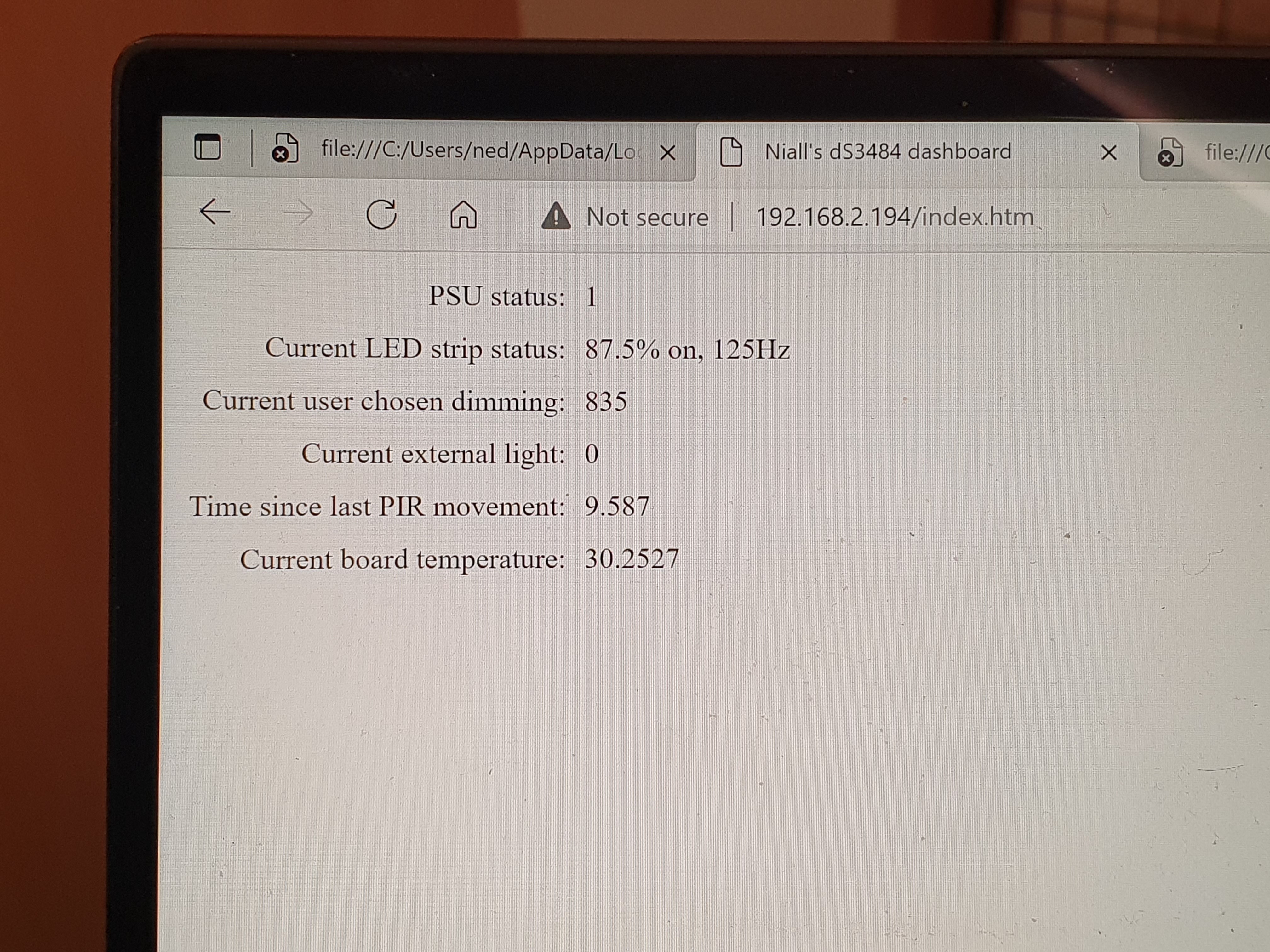
All in all apart from the occasional head scratch all this work went smoothly, albeit that the low resolution software PWM dimming isn’t really good enough for my house build, so I’ll need something better. I didn’t get around this weekend to integrating this with Home Assistant, so next weekend that’s exactly what I’ll be doing: I’ll probably write a very simple local push integration for Home Assistant that lets this dScript push status changes to Home Assistant. I may also allow Home Assistant to override the board’s default logic e.g. put lights to 100%, or turn everything off.
Something else I’ll need to make a start on is researching alternatives for home automation. Something rather noticeable in this prototype is basically all the analogue inputs are full already, and given each of these boards costs at least €75 inc VAT, that’s rather too much money to be expending per room in the house. I need something much cheaper which can also do high resolution hardware PWM dimming and isn’t a pain to wire up and/or configure. I’m also minded that I have a bunch of sensors I want to test for my house build which require I2C, and the Devantech board doesn’t expose that.
Don’t get me wrong here, this Devantech board is absolutely great for automating high current stuff such as immersions, pumps, home heating water valves, that sort of thing – anything involving 12v DC or 230v AC and lots of current. The volt free inputs are perfect for wall switches etc. but not suited for wiring in Arduino/RaspPi focused sensors. This implies that my sought after cheaper alternative probably is going to be an Arduino or Raspberry Pi, exactly because the whole breakout board sensor ecosystem is designed around them, but also because they have the deep software support for enthusiasts which makes the experience a whole lot less painful than is usually the case with embedded systems programming.
| Go to previous entry | Go to next entry | Go back to the archive index | Go back to the latest entries |