Welcome to ned Productions (non-commercial personal website, for commercial company see ned Productions Limited). Please choose an item you are interested in on the left hand side, or continue down for Niall’s virtual diary.
Niall’s virtual diary:
Started all the way back in 1998 when there was no word “blog” yet, hence “virtual diary”.
Original content has undergone multiple conversions Microsoft FrontPage => Microsoft Expression Web, legacy HTML tag soup => XHTML, XHTML => Markdown, and with a ‘various codepages’ => UTF-8 conversion for good measure. Some content, especially the older stuff, may not have entirely survived intact, especially in terms of broken links or images.
- A biography of me is here if you want to get a quick overview of who I am
- An archive of prior virtual diary entries are available here
- For a deep, meaningful moment, watch this dialogue (needs a video player), or for something which plays with your perception, check out this picture. Try moving your eyes around - are those circles rotating???
Latest entries: 
Word count: 2645. Estimated reading time: 13 minutes. Friday 16 January 2026: 22:05.
I’m now into the final A4 page of todo items! To be honest, I’ve not been trying too hard to find new employment, I haven’t been actively scanning the job listings and applying for roles. That will probably change soon – as part of clearing my multi-page todo list I finally got the ‘kitchen sink’ CV brought up to date which took a surprising number of hours of time as I hadn’t updated it since 2020. And, as the kitchen sink CV, it needed absolutely everything I’d done in the past five years, which it turns out was not nothing even though my tech related output is definitely not what it was since I’ve had children. So it did take a while to write it all up.
Still, I have a few more months of todo list item clearance to go yet! The next todo item for this virtual diary is the insulated foundations design for my house build which my structural engineer completed end of last November. I’ll also be getting into my 3D printed model houses as I’ve completed getting them wired up with lights.
To recount the overall timeline to date:
- 2020: We start looking for sites on which to build.
- Aug 2021: We placed an offer on a site.
- Jul 2022: Planning permission obtained (and final house design known).
- Feb 2023: Chose a builder.
- Feb 2024: Lost the previous builder, had to go get a new builder and thus went back to the end of the queue.
- Aug 2024: First draft of structural engineering design based on the first draft of timber frame design.
- Nov 2024: Completed structural engineering design, began joist design.
- Mar 2025: Completed joist design, began first stage of builder’s design sign off.
- Jun 2025: First stage of builder’s design signed off. Structural engineering detail begins.
- Nov 2025: Structural engineering detail is completed, and signed off by me, architect, and builder.
- Dec 2025: Builder supplies updated quote for substructure based on final structural engineering detail (it was approx +€20k over their quote from Feb 2024).
- We await the builder supplying an updated quote for superstructure … I ping him weekly.
We are therefore on course to be two years since we hired this builder, and we have yet to get them to build anything. As frustrating as that is, in fairness they haven’t dropped us yet like the previous builder, and I’m sure all this has been as frustrating and tedious for them as it has been for us. As we got planning permission in July 2022, we are running out of time to get this house up – the planning permission will expire in July 2027 by which time we need to be moved in.
All that said, I really, really, really hope that 2026 sees something actually getting constructed on my site. I was originally told Autumn 2024, we’re now actually potentially Autumn 2026. This needs to end at some point with some construction of a house occurring.
The insulated foundations detail
I last covered the engineer’s design in the June 2025 post, comparing it to the builder’s design and the architect’s design. Though, if you look at the image below it’s just a more detailed version of the image in the August 2024 post. Still, with hindsight, those were designs, but not actual detail. Here is what actual detail looks like:

We have lots of colour coded sections showing type and thickness of:
- Ring beams (these support the outer concrete block leaf and outer walls)
- Thickenings (these support internal wall and point loads)
- Footings (these support the above two)
As you can see, the worst point load lands in the ensuite bathroom to the master bedroom – two steel poles bear down on 350 mm extra thick concrete slab with three layers of steel mesh within, all on top of an over sized pad to distribute that point load. This is because the suspended rainwater harvesting tanks have one corner landing there, plus one end of the gable which makes up the master bedroom. The next worst point loads are under the four bases of the steel portal frames, though one is obviously less loaded than the other three (which makes sense, only a single storey flat roof is on that side of that portal frame). And finally, there is a foot of concrete footing – effectively a strip foundation – all around the walls of the right side of the building, this is again to support the suspended rainwater harvesting tanks.
Let’s look at a typical outer wall detail:

Unsurprisingly, this is identical to the standard KORE agrément requirements diagram I showed in the most recent post about the Outhouse design (and which I still think is overkill for a timber frame house load, but my structural engineer has no choice if we are to use the KORE insulated foundations system). Let’s look at something which we haven’t seen before:

This is for one of the legs of the portal frame next to the greenhouse foundation, which has 200 mm instead of 300 mm of insulation. Much of the weight of the house bears down on those four portal frame legs, so unsurprisingly at the very bottom there is firstly a strip footing, then a block of CompacFoam which can take approx 20x more compressive load than EPS300, then 250 mm of double mesh reinforced concrete slab – you might see a worst case 3000 kPa of point load here, which is of course approximately 300 metric tonnes per sqm. I generally found a safety factor of 3x to 10x depending on where in their design, so I’m guessing that they’re thinking around 100 metric tonnes might sometimes land on each portal frame foot.
Actually, I don’t have to guess, as they supplied a full set of their workings and calculations. I can tell you they calculated ~73 kg/sqm for the timber frame external wall and internal floor, and ~42 kg/sqm for internal racking walls. The roof they calculated as ~140 kg/sqm, as I had said I was going to use concrete tiles. Given these building fabric areas:
- 150 sqm of internal floor = 11 tonnes
- 393 sqm of external wall = 29 tonnes
- 270 sqm of roof = 48 tonnes
… then you get 88 tonnes excluding the internal racking walls, most of which bear onto the concrete slab rather than onto the portal frames. So let’s say a total of 100 tonnes of superstructure. As you can see, even if the entire house were bearing on a single portal frame leg instead of across all four legs, you’d still have a 3x safety margin. With all four portal frame legs, the safety margin is actually 12x.
Speaking of heavy weights, we have a hot 3000 litre thermal store tank to support where the foundation must deal with ~80 C continuous heat. EPS doesn’t like being at 80 C continuously, so if we had hot concrete directly touching the EPS, we were going to have longevity problems. This did cause some thinking caps to be put on by engineer, architect and myself and we came up with this:

As you see, we introduce a thermal break between the hot concrete slab and the EPS using 50 mm of Bosig Phonotherm, which is made out of polyurethane hard foam. Polyurethane is happy with continuous temperatures of 90 C, and it drops the maximum temperature that the EPS sees to around 70 C. It is also happy getting wet, it can take plenty of compressive loads, and its only real negative is that it is quite expensive. Unfortunately, I’m going to have to use a whole bunch of Bosig Phonotherm all around the window reveals, but apart from the expense it is great stuff to work with and it performs excellently. To the sides, the thermal break is the same 30 mm Kingspan Sauna Satu board which is the first layer of insulation within the thermal store box: Satu board is a specially heat resistant PIR board, and as it is expensive we use conventional PIR board for most of the thermal store insulation. Similar to the Bosig Phonotherm, the Satu board brings the temperature down for the outer PIR, also to about 70 C.
Finally, let’s look at some detail which also delayed the completion of this insulated foundation design: the insulated pool cavity:

The challenge here was to maintain 200 mm of unbroken EPS all the way round whilst also handling the kind of weight that 1.4 metres of water and steel tank and the surrounding soil and pressure from the house foundations will load onto your slab. Solving this well certainly consumed at least six weeks of time, but I think the job well done. Given that my engineer did not charge me more than his original quote – and he certainly did more work than he anticipated at the beginning – I cannot complain. The quality of work is excellent, and I’m glad that this part of the house design has shipped finally.
3D printed model house
Eighteen months ago I taught myself enough 3D printing design skills that I was able to print my future house using my budget 3D printer. It came out well enough that I ordered online a much bigger print in ivory coloured ASA plastic, which I wrote about here back in June 2024. In that post, I demonstrated remarkable self knowledge by saying:
When all the bits arrive, if a weekend of time appears, I’ll get it all cut out, slurry paste applied where it is needed, wired up and mounted and then put away into storage. Or, I might kick it into the long touch as well and not get back to it for two years. Depends on what the next eighteen months will be like.
Writing now eighteen months later … indeed. After the model arrived, I then ordered a case for it which I wrote here about in August 2024, where I wrote:
The extra height of the case will be used by standing each layer of the house on stilts, with little LED panels inside lighting the house. You’ll thus be able to see all around the inside of the model house whilst standing instead the actual finished house. It may well be a decade before I get to assemble all the parts to create the final display case, or if this build takes even longer I might just get it done before the build starts. We’ll see.
I was being overly pessimistic I think by this point, though had the house build started sometime between then and now maybe I’d be too occupied working on the house to work on a model house. Anyway, all that’s moot, because witness the awesomeness of the fully operational house model:
From all sides:


And with the case on:

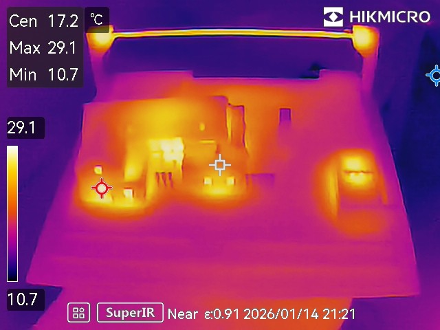
To make sure there would be no thermal runaway problems which might melt the house etc:


Looks like on full power after twenty minutes with the case on we get a maximum 54 C or so. Now, it being winter here, the surroundings are cold so that could easily be 10-15 C more in summer. But it wouldn’t matter – ASA plastic has a glass transition temperature of 100 C. And, besides, we’ll never run the lights at full power, they’re too bright so they will be at most on a 33% PWM dimming cycle.
The lighting is provided by these COB LED strips with integrated aluminium heatsink made by a Chinese vendor called Sumbulbs. You can find them in all the usual places and you can buy a dozen of them for a few euro delivered. They are intended to be soldered, and you can see my terrible soldering skills at work:
The layers of the house are separated by cake stands:
And with the case on:
And finally, showing both the cake stands and the COB LED light strips:

You’ll note that not all the COB LED strips have the same brightness. With hindsight, this is very obvious – that darker one to the bottom right clearly has only a few LEDs spaced well apart, whereas the top roof ones especially are densely packed LEDs. I mainly chose the strips at the time based on what would fit the space available rather than any other consideration. Anyway, I don’t think it matters hugely, but perhaps something to be considered by anybody reading this.
In case you’re wondering, total costs were:
- €150 inc VAT inc delivery for the 3D print.
- €200 inc VAT inc delivery for the cases (this includes the small case below).
- €20 inc VAT inc delivery for the cake stands, most of which I did not use.
- €10 inc VAT inc delivery for the COB LED strips, and I also only ended up using a few of these and I have loads spare.
So I’d make that about €350 inc VAT inc delivery, plus a whole load of my time to design the 3D print and do all the wiring. I intend to mount it into the ‘house mini museum’ which will memorialise how the house was designed and built.
3D printed model site
You may or may not remember that using my own personal 3D printer I had also printed the whole site. This isn’t very big as it’s limited by the 20 cm x 20 cm maximum plate on my personal 3D printer, but it gives you a good sense of how the house and outhouse frame the site. Anyway, I started by inserting 4 mm LEDs throughout the house and outhouse:
I also designed a little stand for ‘the sun’ at the south side of the site, which is another Sumbulbs COB LED strip with integrated aluminium heatsink (the same used throughout the big house model):
And turning up ‘the sun’ to full power:
With the roofs off:

And finally the thermals:


Once again, no issue there even on full power with the case on after twenty minutes.
This model certainly cost under €50 inc VAT inc delivery, maybe €40 is a reasonable estimate. Most of the cost was the case, and of course my time.
My plan for this model is that it will be in daylight when it is daylight outside, and go to night time when it is night time outside, and it’ll also be mounted in the mini house museum. Should be very straightforward. Just need to get the real house built.
I continue to ping the builder weekly, and maybe at some point he might pony up a final quote and then it’ll be off to the races after two years with him, and three years waiting for builders in general. Here’s hoping!
Word count: 25032. Estimated reading time: 118 minutes.
- Summary:
- A detailed historical narrative spanning 1815-1915 is presented, tracing how one branch of the author’s family lost their fortune derived from Caribbean sugar plantations. The decline of landed aristocracy through economic shifts, policy changes, and poor investment decisions is examined. Parallels are drawn between that era and current times, with speculation offered about AI’s role in creating a new technological aristocracy and its societal implications.
Friday 9 January 2026: 00:26.
- Summary:
- A detailed historical narrative spanning 1815-1915 is presented, tracing how one branch of the author’s family lost their fortune derived from Caribbean sugar plantations. The decline of landed aristocracy through economic shifts, policy changes, and poor investment decisions is examined. Parallels are drawn between that era and current times, with speculation offered about AI’s role in creating a new technological aristocracy and its societal implications.
This essay is about how my personal family, especially one branch of it, got from where they were at the beginning of the Second British empire, which began after the defeat of Napoleon in 1815, until now. The period 1815-1915 is peculiarly similar to the period 1945-2045 (so far) with a remarkable repetition of resonances, so what keeps drawing me back to thinking about that earlier period is due to me thinking hard about what is to come next for us right now. Yes, we know the broad sweep of history from the history books. But in terms of knowing what to do for my family now and next, personalising history into the context of my historical family from the 1815-1915 period seems worth doing.
Also, to be honest, AI has just very recently revolutionised parsing
historical records. I had always assumed that record keeping before the 20th
century just wasn’t very good. In fact, record keeping since 1750-1800
onwards has been surprisingly complete in most of the western world, it’s
just that the data was locked in hard to parse records distributed across
many small places. AI in the last few years has become better than certainly
this human’s ability to decipher ancient hand writing, which has turned all
the digitised old records into far more useful resources because now the
text extracted from them is accurate, but also because AI can then summarise
that extracted text into comparable text corpora. Also, there has been a
concerted effort to digitise things like headstones in cemeteries, and with
all that information sites like ancestry.com
have made it surprisingly
straightforward to assemble your entire complete family tree going back to
1750 or so. To that end, here are the sixty-four sixth generation away
people who contributed genes to my children (and my thanks to my Aunt Ruth
and Megan’s mother Sara for getting me started with creating this tree),
and my apologies in advance if your web browser doesn’t yet support the
experimental scroll-initial-target:nearest CSS feature to initially
scroll this very wide PNG to centre on page load (if it doesn’t, you’ll
need to scroll this image right to reach the centre):

There are five people missing – this is because ancestry.com wants me to pay them money to establish those, and because I don’t want to pay them money, I’ll be leaving those empty until the ‘free ancestry.com lottery’ gives me them for free (to drive engagement, they drip feed you free data each day to make you log in frequently). But I can tell from their advertising being pushed at me that they have the data not just for those missing five people, but also certainly their parents and possibly their grandparents. So, given enough time or paying ancestry.com money, I think I could create a reasonably probably complete list of the 256 people which make up the eighth generation away ancestors. That’s pretty good – that’s everybody from about 1750 until now, so 275 to 300 years, barring a few likely mistakes where I’ve misconnected children to parents. Within that list, I know birth, death and marriage dates, the number of children and number of spouses, but I often also know occupations, and a surprising amount about internal and international travel (before the 20th century, immigration logs were public, but also children’s birth certificates state location).
The picture which emerges from our complete set of ancestors is very much representative of European colonial imperialist expansion during that period. As that will also set the stage prior to when this essay will begin in earnest from 1815 onwards, it is worse briefly recounting.
What our ancestors were doing towards the end of the First French Empire (before 1815)

What AI thinks British Colonial America looked like before independence
Megan’s side of the family before 1815
In terms of percentage of new arrivals relative to the existing population, the United States has had three historical bursts of immigration:
- 1600-1770 (pre-independence), after which immigration was near zero until …
- 1830-1900 much of which was driven by famine in Europe followed by the Long Depression, after which …
- 1950-2010 was driven by the United States replacing Britain as the dominant world economic hegemon, and therefore attractive to global economic migrants.
You can read lots more detail at the Wikipedia page on the history of immigration into the United States, and no I didn’t mistype the third burst ending in 2010 – most US citizens currently think floods of immigrants are entering right now, but the statistics show that the third burst did indeed peak in 2010 and since then ever fewer people relative to the current population have relocated to the United States. If history repeats, it’ll be another fifty years before the next burst begins.
Interestingly, most of my wife’s ancestors were already in the US when it was still a British colony, so they arrived during the pre-1770 immigration period from what appears to be mostly British Presbyterian stock (who at the time were being persecuted for their religious beliefs). That was surprising to me and to her – she had thought herself comprised more of post-1830 immigrants. Yes there are a few of those in her bloodlines, but the bulk is undoubtedly the many young British people who sold themselves into indentured labour to pay for transport to the colonies with the hope of better economic opportunities. After their indentured contract was served, they generally purchased farmland typically around Maryland, Carolina and Virginia where cash crops for export were grown. One thing very noticeable on Megan’s side of the tree is the number of children her ancestors had who survived into adulthood compared to my side of the tree – also, whereas a majority of the women my side of the tree died in childbirth, on her side I’d estimate two thirds or more made it into relatively old age. This suggests that while life was hard in the United States, it was worse in Europe, at least for our ancestors. Another thing which stands out is that in my side of the family, there was always the ‘youngest son’ or ‘junior branch’ problem because the eldest sons would get all the inheritance, so special effort and arrangements had to be made to find livelihoods and wives for the youngest sons. In contrast, in Megan’s side of the family all the children bought farmland no matter how senior or junior apparently with relative ease – I would assume that unlike in Europe where all the land was taken and very little was available for purchase, in the US at that time you simply took new land from the native inhabitants which made it affordable to all children.
Indeed, the state of Indiana is so named because it was originally part of the Indian Reserve of 1763 (about which you can read lots more here). That area underwent a period of violent instability caused by British and American armies fighting each other and the native tribes up until 1812 when the British yielded, and the US Congress sought to ensure a bulwark against any further instability going forwards. They made available lots of farmland on the now disentailed Indian Reserve at low prices, and a majority of Megan’s ancestors appear to have taken up the offer – there is a noticeable movement all at once from all over then British Colonial America of all the generations whose children and grandchildren were yet to marry each other to lands within or nearby the state of Indiana. And there they have remained ever since, with surprisingly limited relocation until very recently, mainly growing food or providing services to farmers such as religious guidance (mainly Lutheran), blacksmithing or dentistry for about two hundred years. As far as I can tell from this vantage point, there wasn’t a huge disparity in economic outcomes across all Megan’s ancestors – they all appear to have started from roughly similar circumstances, some were a generation or two earlier to wealth and education and moving up the value chain than others, but they all moved with remarkable uniformity relative to my ancestors who are far more a hotchpotch. I guess that’s what the American Dream once was: most bar the dispossessed native inhabitants had things, on average, better than their ancestors for enough generations it became an expected truism.
My side of the family before 1815
Megan’s ancestors were remarkably uniform, whereas mine are quite the smorgasbord. Like Megan’s ancestors, one quarter of mine on my Presbyterian mother’s father’s side at that time were also low church Protestants of varying kinds. I can see brothers and sisters of those ancestors emigrating to America and the other British colonies, however obviously my specific ancestors did not. As far as I can tell, the reasons mine stayed were because they were the eldest or second eldest son and thus had an inherited livelihood, or else they married an eldest or second eldest son. As with Megan’s ancestors, men tended to reach their seventies and the women who didn’t die in childbirth usually made their sixties. Subjectively speaking, it looks like life around 1800 was a bit better for the Americans than for this quarter of my ancestors, but only by a bit.
A second quarter on my Catholic mother’s mother’s side did not do well, at least as far back as I can currently see. My grandmother’s father, a gardener for a priest, died in his forties. Even before that during the 19th century, they were lucky to make it into their fifties before death, and life was hard – I can see they had to share a small house with another poor family in the 19th century. They still had it better than many on the island of Ireland at the time – you didn’t want to be a sub-sub-tenant farmer as an example, they were mainly the ones who died from starvation in the potato famine. They were so poor that there were no choices other than to starve to death – emigration was an option only for the slightly wealthy upwards. This branch of my ancestors weren’t that poor, they were maybe one or two rungs above, they definitely could afford an occasional steamer to America – as evidenced by the location of my great grandfather’s demise (San Francisco).
The next quarter were mostly Catholic on my father’s mother’s side. They were a mix of middle class Catholic French Belgians and middle class Protestant probably Methodist English from Suffolk, with jobs such as tailor, composer or teacher. They generally had long healthy lives and had sufficient wealth that all of their relatively few children (by the standards of that time) who reached adulthood could be well educated and given a good start in life. Indeed if you squint a little (childhood mortality was high back then), the children born around 1800 to that quarter of my ancestors had a similar lifestyle to middle class people today – they travelled quite a bit for pleasure, attended leisure activities such as orchestral recitals, and clearly felt a security about life and living which the previous two quarters of my ancestors never knew. The only major obvious difference is rates of childhood mortality, otherwise they look surprisingly contemporary in terms of behaviour, pastimes and inclinations, at least from this distant perspective.

What AI thinks is 'aristocracy'
The final quarter is by far the best documented – mostly due to the work of my Aunt Ruth thank you! – but also because they were famous at the time due to being either aristocracy or wealthy, and hence lots of ink got spilled about them in lots of places over the centuries in everything from wood carved caricatures to tax receipts. Back in 1800, two of my ancestral lines combined, one was aristocratic, well regarded, and sometimes wealthy but generally plagued with money troubles; the other until now we had thought were wealthy industrialists my ancestors had married into, but I now think were actually also ruling elite but recently dispossessed of their power which caused them to take a big gamble which paid off, but at the expense of thousands of lives – all the other bloodlines they married into were usually middle class with good jobs like the previously described Catholic quarter – though generally Anglican/Methodist/Lutheran Protestant rather than Catholic. Of the aristocratic bloodline, let us begin with my specific ancestor Sir William Douglas (1730-1783) who was a Member of Parliament for Dumfries between 1768 and 1780, and you can read his Hansard history here. Before 1833, most members of Parliament for a given constituency were chosen by the big landowners of that constituency, which in this case was primarily Charles Douglas, Duke of Queensbury. To be clear, a Member of Parliament back then did NOT work for the people, they worked for and had their salary paid by the big landowner, and they had to do what they were told or they were replaced. The Duke was very keen on my ancestor William who also ran his estate for him as a manager, and left £16,000 to him on his death in 1778, an enormous sum (about £39 million in 2024 sterling by the wages deflator).
")
Sir William Douglas (1730-1783)
William until that point had never been wealthy. His father, Sir John Douglas, also Member of Parliament 1741-1747 but for Dumfriesshire which neighbours the Dumfries constituency, had died in disgrace in debtor’s prison, which was almost never used on members of the aristocracy except in the very most severest and recalcitrant cases (he also got himself locked in the Tower of London pending execution for High Treason against the Crown in 1746, but I digress). William and his siblings, having had no other members of family willing to take them in, ended up being raised with his tutor’s family which was not a wealthy upbringing, and William had to take a job which was as manager of the Duke’s estate and succeeding his father’s role Member of Parliament for that constituency – so he worked for a living and had done so all his adult life. Unfortunately, so overjoyed was he on receiving such a life changing sum of money after a lifetime of severe money issues, he had a fit of apoplexy and died upon receiving the good news. That inherited fortune then formed the basis for his eldest sons’ livelihoods, which meant that my specific ancestor Lord William Robert Keith Douglas (1783-1859) who was the youngest son (and therefore without a livelihood) therefore also needed to take a job like his father. By the time he was an adult, his patron who had inherited the previous Duke’s lands and titles was Walter Francis Montagu Douglas Scott, Duke of Buccleuch and Queensbury, the richest man in Scotland (an actual millionaire in the money of the time, the current Duke who is that Duke’s lineal descendent remains today the richest man in Scotland owning about half the total land area). This Duke did not like my ancestor as much as the previous Duke and often grumbled publicly about him, however he still sent him to Parliament for Dumfries between 1812 and 1832 after which the rotten borough system was abolished, and Hansard has written up an excellent summary of his political life here.
The younger Douglas was considerably more active in Parliament than his father, of which there is no record of him ever speaking in any debate ever. He was initially a pro-Catholic, pro-reform, pro-free trade member of the Tory party, and seems to have had enough talent at it that he became noticed by Walter Irvine (1747-1824) as a potentially suitable husband for his eldest daughter, Elizabeth Irvine (1798-1864), which brings me onto the most sordid and sad part of my ancestry.
John Irvine (1720?-1786), the father of Walter, was a Chancery Clerk in Edinburgh, which then was a civil servant who manages the local legal affairs of the monarch, and is custodian of the seal of the monarch for that locality. Such an establishment role is surprising to me for somebody with the surname of Irvine, as that clan’s leading people were strongly associated with Jacobitism. We know John’s family came from around Kingscairn Mill near Crail just north of Dunino in Fife – this is why later they would buy all the lands surrounding there in the form of the Grangemuir estate. We know several other Irvine families lived in a cluster in lands immediately adjacent, and those definitely were involved in the 1745 Jacobite rising because we have records of it. John’s father (probably also called John) had enough money to afford to educate and send his son to Chancery Court, which suggests something better than a tenant farmer. But I’ll speculate on that later.
, or more likely Sir John Douglas (1708-1778), taken by me during Christmas from the painting hanging in my father's house")
John Irvine (1720?-1786), or more likely Sir John Douglas (1708-1778), taken by me during Christmas from the painting hanging in my father's house
(The person in this mid 18th century painting is wearing a type of wig called a ‘peruke’, which suggests an occupation in law. It was therefore assumed that this is a painting of John Irvine as he would have worn such a wig at the Court of Chancery. However my grandfather disagrees, and thinks this painting is actually of Sir John Douglas, the same one incarcerated for High Treason in 1746. I have compared this painting to other paintings of Sir John, and I agree that there is a resemblance. Why Sir John was wearing this particular wig at such a young age I cannot say)
A Clerk of the Chancery would have been a very solid upper middle class role with access to and visibility into ruling elites and their information, and with enough income that investing it would be both a concern and a possibility. The Treaty of Paris 1763 brought several Caribbean islands under the control of the British after a century of them being repeatedly re-conquered by Dutch, French and British navies, and to establish a bulwark against another invasion the British government divided the island into plots and sold them to retail investors (see https://en.wikipedia.org/wiki/History_of_Tobago for detail). John Irvine along with his sons John, Charles and Walter took out a mortgage from a London financier named Mr Rustin and entered a partnership with a Mr Leith to purchase and for the sons to personally occupy a few of these plots in 1768. They then purchased and proceeded to expire thousands of African slaves to work the land to grow cotton, without much profit. A banking crisis in London in 1772 put many of the planters into financial hardship; in 1778 the partnership with Mr Leith was broken up as the economic situation worsened due to war in the American colonies; in 1781 the French recaptured Tobago, and at this point a majority of the original planters gave up and sold what little value remained. My ancestors Walter and Charles (by then their brother John had died from suspected malaria) proceeded to buy up all this land at firesale cheap prices to create very large plantations which would shortly greatly benefit from economies of scale.
It would appear the bad times continued for them until the 1789 French Revolution which spread disarray throughout the French colonial empire, and specifically the most profitable possession in the French empire Saint-Domingue, today known as Haiti. Production across the French Caribbean collapsed over the next few years, and my ancestor in possession of large, very efficient, estates in Tobago was unusually well placed to benefit from it. In the next ten years their plantations switched over to sugar and rum production, and over a quarter billion pounds in today’s money was pocketed as profits by the two brothers in a few short years. If this seems fantastical, consider crypto billionaires today: the vast majority of people who were involved in crypto before it ballooned never made anything from it. A few very lucky – and I want to emphasise it was luck not skill nor hard work – people just happened to be in the right place and right time to receive an enormous windfall, and had any one thing been different they would have gotten absolutely nothing. Like crypto billionaires today, my ancestor was astonishingly lucky (in financial terms). Using his new found vast wealth, in 1796 he purchased Luddington House from a Richard Wyatt of Egham as his British residence, a very fancy property, in Surrey south west of Heathrow Airport. This is it today (it is now an apartment complex) and it retains all the original 17th century buildings and layout, as it is a protected building:


Luddington House today which is home for lots of families; in 1800 just one family (and their servants) lived in all those large buildings
Indeed, such were the profits from the sugar plantations that the British government swiftly imposed steep import tariffs to capture much of those profits and thus removing that windfall from the sugar plantation owners (in those days, most government income came from tariffs and duties, income taxes were only levied during times of war). My ancestor Walter Irvine realised he now needed to be near London to protect his interests against further government intervention, so in 1796 he moves permanently to Britain into his new house, and the following year marries Catherine Gordon, the second eldest daughter of a neighbouring Tobago plantation owner Alexander Gordon, with him aged fifty and her aged thirty-two. I’ll do some speculating on her later, but almost certainly Walter would have known Catherine for some years before marriage as the Tobago ‘dinner party scene’ involved the wealthy having parties in each other’s houses throughout each year, and I can find no reason why as neighbours the Irvine and Gordon estates would not have socialised with one another. In 1798 his brother Charles dies intestate, so Walter ‘ends up with’ all the plantation wealth (I put that in quotes, because a later legal case alleged he purloined his brother’s estate for token payments to his brother’s family). He then proceeds to use that vast wealth to influence government direction, successfully stalling for fifteen years what would become the Slave Trade Act of 1807 in the House of Lords after it was originally passed by the House of Commons in 1792. It was probably only eventually released out of the Lords because of events on the Continent, where Britain sought a moral win over the rising Napoleonic empire, and that gave the abolitionists enough momentum to get it out of the Lords and into law. Now that the trading of slaves was illegal from 1807 onwards, that began the end of the slave plantation era which would take another century to be fully enacted.
According to the West-India Commonplace book report published in 1812, up to 1807 the two least worst for the slaves plantation islands in the British Caribbean were St. Vincent and Tobago in that order. In both, due to how they were set up and planted by mostly Scots mostly junior branches of aristocratic or merchant families, a culture of investment in machinery, automation and the education and training of the slaves to maximise profits had taken hold, rather than maximising profits by working them to death which was common elsewhere. As that report describes, unlike in the other islands, in both islands the population were usually well treated enough to grow naturally and therefore exported surplus slaves to the other islands, the worst of which would annually kill 2-4% of their slave populations from overwork and therefore needed to constantly buy more to remain viable. Unlike elsewhere, in St. Vincent and Tobago the managerial class of slaves were routinely taught to read and write and could accumulate assets which could then be used to buy their own or another’s freedom, or willed to others on death. That report reckoned from a purely economic perspective that St. Vincent and Tobago’s practices as best in class due to being the most productive once all costs were considered, and that their practices should be replicated elsewhere. Thanks to an enthusiastic society of local historians, Tobago has since built up an extensive and detailed academically researched history of the plantations on their island, and a good summarising book on that research can be found in 2008’s The Changing Society of Tobago, 1838-1938: A Fractured Whole, which can be downloaded and read in full from here. Where later I make statements about life in Tobago, it will either come from that book or from the Tobago historical society’s Facebook group.
I don’t want to make the relatively better conditions on Tobago sound like any form of excuse making for this branch of my ancestors. Walter Irvine had at least one child named Betsy from his slaves before he married Catherine Gordon, and could have been the father of a second named Mary. Catherine, his future wife, would almost certainly have known both daughters personally for some years before marrying Walter, and it appears to have not been a showstopper for her – slave master men having children with their female slaves was quite common in Tobago and indeed in most of the colonial plantations. Both girls, especially Betsy, received life changing fortunes from his will on death, and Betsy who comes across as a favourite relocated permanently to Britain with him in 1796 aged eight and stayed there until at least his death in 1824. Possibly, Betsy’s mother had died during childbirth, as Walter’s will awards a fine cash sum to Mary’s ‘negro mother’ (I quote here from the will), but no mention of Betsy’s mother was made. We haven’t found evidence that Betsy ever married, but Mary did marry and she is the ancestor of a good number of people living throughout the Caribbean today.
Walter’s main plantation is today a luxury resort hotel owned by a descendent of slaves who worked there with all the sugar plantation buildings and machinery preserved as features – the sugar mill, once the largest on the island, now houses the hotel restaurant, and the loading docks on the beach for the transport ships have been converted into a promenade for sun loungers. Here it is today:

Mount Irvine, Tobago
Obviously it was rather more grim in 1790, but I have been unable to find a realistic drawing or painting from that early – drawings and paintings from then were heavily sanitised and not at all representative. The most realistic I can find is from around 1900, long after slavery was abolished and by which time almost all the plantations were owned and operated by former slaves and much labour saving automation had been introduced. Still, it’s better than nothing, and all these are of Tobago and thanks to the Tobago Historical Society:
 Where the sharecroppers slept around 1900 in Tobago |
 Loading the cut down sugar cane, also around 1900 |
 An example of where the plantation owners lived in comparison to the sharecroppers |
To wrap up this section, I’d like to engage in some pure speculation. I find it worth remarking upon that an Irvine marries a Gordon, and their child marries a Douglas. The reason for this is history: my junior branch Douglas ancestors without doubt were managing the same estate of the Duke of Queensbury as similarly junior branch Irvines in the mid 18th century. They were both employed by the Duke at the same time in the same place in the 1760s – this is documented fact. I also found some evidence that junior branch Gordons were also present in the 1760s on that estate at least some of the time, also in a working capacity. Where I would speculate is about the milieu of interaction between all these junior branches – the leaderships of Irvine/Irving, Douglas and Gordon clans had all been by each other sides for centuries beforehand, with very extensive intermarriage and interrelationships both business and personal. That would have spilled into the tenant farmers, or at least their ‘tacksmen’ (the managerial class). There was without doubt a wide network of second and third cousins at least some of whom regularly interacted. Where I speculate is to what extent, and how much it meant to them to ‘marry within’ versus ‘marry out’? To what extent did the ambitious of these junior branches set out to advance the British Empire and their own wealth? How much did they collaborate as a network of Scotsmen and Scotswomen in doing so?
I have absolutely no idea if John Irvine Sr was a tenant farmer under an Irvine chief with no blood ties to that chief and had simply taken the surname, or if a junior branch of the Irvine clan leadership thought it best to vacate their ancestral lands in Drum or Dumfries and ‘disappear’ into Fife (where historically there are zero Irvines) after the 1715 Jacobite rising went against them. We do know a wealthy John Irvine was married to a Helen Ross in Dunino in 1726, and there is no mention of any Irvines in that locality before that date. It would of course, at the time, been wise to not mention loudly their origins, and my John Irvine working at Chancery Court would definitely not want to ever mention at work the word ‘Jacobite’. I suppose we will never know for sure what type of Irvines they were, still:
- The Jacobite rising of 1745 had ended the old Clan system which had rendered impotent all the Clan Chiefs thereafter – also, the Scottish independence movement was now clearly spent. The dispossessed children of clan ruling elites of Scotland began to look outwards to secure their futures.
- There were Douglases, Irvines and Gordons all in the same place in the 1760s,
barely two decades later.
- The Tobago plantation opportunities appeared towards the end of the 1760s and
various Douglases, Irvines and Gordons all took up the offer.
- The Tobago dinner party scene had all these junior branch members regularly
getting drunk together, where almost certainly shared clan history and Scotland
would have been a frequent topic of discussion.
- After fortunes were made, at the end of the 1790s an Irvine marries a Gordon (who herself was the junior branch aristocratic product of a Gordon and McCulloch), and twenty years after that their child marries an aristocratic Douglas. That does strongly hint that these Irvines were former clan leadership who were disillusioned or dispossessed by the 1715 rising, and now were marrying into the Scots side of the British aristocracy.
To be clear, I am 100% speculating here, there is no proof I can find. It just seems remarkably coincidental that some Douglases, Irvines and Gordons definitely were all in the same place in the 1760s just before they bought plantations in the colonies – though, again, there is no proof that it was our specific people bar Sir William Douglas and his children at the Duke’s estate at the time. And those Scots aristocratic junior branches would go on to marry off each other’s children during the next sixty years, which feels like there was at least some ad hoc plan or at least mutually shared direction to all embark upon.
To end on even more specious speculation, I wonder what the psychological effect of repeated defeats of Scots independence across a century were on the strongest believers? Did they take their frustrations and bitterness and become a tip of the British Imperial spear, doing to colonised peoples what the English had done to the Scots for so many centuries? I wonder if all those junior branches of all those leading Scots clans ended up doing what they did to slaves repeating exactly what had been done to their ancestors as some sort of trauma induced repeating loop? It’s all very, very sad.
1815-1915: Pax Britannica

What AI thinks 'Pax Britannica' looks like
So now we’re getting into the meat and bulk of this essay: the century of Pax Britannica, a period of sustained lack of major war caused by a single hegemonic power dominating everything around it. To remind readers of why I find resonances between that period and our own Pax Americana 1945-2045 beyond the sustained lack of war:
| Pax Britannica | Pax Americana | |||
|---|---|---|---|---|
| 1815 | Pan-European (Napoleonic) War ends | 1945 | Pan-European (Second World) War ends | |
| 1874 (+59 years) | Long economic depression begins as post-war economic expansion falters | 2008 (+63 years) | Long economic depression begins as post-war economic expansion falters | |
| 1890 (+75 years) | Germany begins to remilitarise in earnest | 2025 (+80 years) | Germany begins to remilitarise in earnest | |
| 1899 (+84 years) | Other European powers begin to remilitarise in earnest in response | Est. 2030-2035 | Other European powers begin to remilitarise in earnest in response | |
| 1914 (+99 years) | Pan-European war begins | Est. 2045-2050 | Pan-European war begins | |
So we have twenty to thirty years remaining before the third World War begins, if the pattern holds. And in case it isn’t obvious why other European powers would begin to remilitarise in earnest in response to German remilitarisation, it’s because due to European history all the other European powers get nervous when Germany has a bigger military than they do. Right now in 2025 Germany has a much less powerful military than any of France, Germany or Spain. But as they keep pouring 5% of GDP into the military, by 2030 their military will begin to look scary and the other European countries will themselves dramatically raise their military spending to ensure Germany doesn’t get too much unopposable hard power. There was an approximate ten year delay in the 19th century, and I see no reason that there won’t be a similar delay in the 21st century – politicians hate making unpopular choices, so they’ll keep kicking that can down the road as long as they can. Still, when it comes to countervailing existential threats, European ruling elites do eventually grasp the thistle.
There are more resonances than just the above however:
The energy supply in the 1800s was transforming from human and animal muscle + wood + wind mix into a steam powered coal fed mix. It is hard to communicate just how profound that was – throughout human history slavery was the norm, not the exception, because it dramatically reduced the cost of the human muscle component. Coal and steam made it economically feasible for the first time in human history to abolish slavery. The ability of steam and coal to substitute for human and animal muscle had profound knock on effects throughout society, not least that average wages began to soar past the cost of barely surviving living for the first time in human history, as we shall see later.
These grand transformations move slowly enough to not be noticeable to most, however the 21st century is also experiencing a transformation of the energy supply from an oil and coal mix to solar PV, which means nearly zero cost electricity during daylight for half or more of the year. Human history has – until now – been one of constant energy scarcity. Even when oil was very cheap in the late 1960s, it was far from being practically free of cost. Solar PV enables genuinely free of cost abundant energy for the first time in human history (even if for only one third of a day), and it will be as profoundly transformative of human society as coal and steam was because we will be able to throw limitless energy at problems in some circumstances.
To give an example of what I mean, as readers may be aware, training AI is very energy expensive, however training can be costlessly paused and restarted around when the sun shines. While the sun shines, energy is free of cost, which means AI can be trained free of cost. That means ever better AI can be trained free of cost nearly infinitely into the future. That, in turn, means those humans best able to wield AI to increase their productivity will be able to demand wages many times more than other human beings. One can thus expect the wealth gap within the meritocracy to continue to increase, with all the profound effects that will introduce, especially as we increase the portion of society and government implemented with AI. It will be a brand new ‘automation wielding’ aristocracy very different from any historical aristocracy, and I am sure they will consider themselves to have a divine right to do whatever they think best as their power and reach grows.
Globalisation then was a tiny fraction of the volume of what it is today, but by 1820 things looked surprisingly similar to 2020 if you did a bit of squinting. By 1820, traveller’s cheques so you didn’t need to bring money with you during your travels had been widely available for fifty years. Would you like a ‘special order’ box filled with stuff chosen personally by you only available on the other side of the planet delivered to your door anywhere in Britain? Yes it would take months, yes it would cost a small fortune, but absolutely that ‘just worked’ in 1820. There were books of available goods in marketplaces all over the world, you could make a list and pay a broker to have somebody at that market obtain your special order, pack it and have it delivered to you, with that box passing through many human hands along well established logistic networks. I know that seems ‘so what?’ to modern readers used to Amazon and Aliexpress, but in all of human history, the periods where special order global logistics worked well are few: the Romans had it for a few centuries, the Mongolians had it for a few centuries, we’ve had it for a couple of centuries, but for most of history for special orders from afar – i.e. sourced from outside your own personal empire – you needed to send one of your men to physically travel there usually with a small army to protect the gold they had to carry with them to pay for the special order, and successfully physically return with the special order i.e. there was not a sophisticated network of brokers and middlemen available to implement seamless special order acquisition and transport. As one can infer, for such a sophisticated network to be sustainable, you need enough special orders constantly moving around the world, and you need sufficient trust between those many human hands that the system ‘just works’. Europe had regained that sophisticated network, having not had it since the collapse of the Mongolian Empire in the 14th century.
By far the most important special order from afar back then was information rather than goods. In 1814 the The Times of London purchased a new state of the art press able to print a thousand pages per hour. Such ever cheaper ever more voluminous printed newspapers aggregated information from all over the world, and disseminated it to an ever widening audience in a way which before 1800 didn’t really happen. This was enormously transformative – until then, only a few ruling elites had much idea of what was currently going on elsewhere right now. Now even a portion of the working classes knew what was happening in say Peru within four months of it happening. This would have huge effects in everything from the rise of Communism to awareness of the realities of war or famine elsewhere in the general population.
Today we have something similar but in some ways opposite happening, but for different reasons: from 2000 onwards there has been a rise of personalised entertainment, personalised information, and personalised world view. You can choose to live in a world full of only the stuff you like to see, and free of anything which might challenge what you already believe. Most have chosen that world, at least partially, and as people retreat ever further into islands of self reinforcing belief and faith it is going to be enormously transformative. Increasingly, only a few and shrinking ruling elites have much idea of what is actually going on across the board as the population’s beliefs and faiths become ever more detached from factual reality. That gives them more power than they have had in centuries, but it is also much harder to reliably use. That suggests more volatility going forth as peoples detached from reality grow ever more numerous and deluded.
In addition to the restoration of an aristocracy and de-education of the masses which are undoings in the 2000s of what was done in the 1800s, there are big economic differences between the 19th and 21st centuries, in this order:
- As alluded to above, the cost of information – especially timely
information – is so much cheaper today than then that I suspect its cost
hasn’t just exponentially decreased, but has hyperbolically decreased (i.e. the rate of decrease
was itself increasing e.g. exponential growth might be something doubling
every time period, whereas an example of hyperbolic growth would be doubling
first period, trebling next period, quadrupling the following period and so on).
I can, almost nearly completely free of cost to me, watch live 4k resolution
videos of a coffee machine on the other side of the planet. Or 3D cat videos.
Or how to construct a jet engine, or a novel retrovirus. Increasingly, I
don’t even need to read instructions in technical jargon, I can have an AI
explain them to me in words I understand and quickly act upon.
- Two of the basic costs of living – food and clothes – are exponentially
cheaper today than then. In the 19th century, food and clothes made up a
significant portion of the cost of staying alive – today, at least in the
three major regions of power Oceania, Eurasia and Eastasia, housing costs
have returned to early 19th century levels in the past twenty years, but the
other two costs of food and clothing are dramatically lower.
- The cost of finished goods is a fraction today of then, and the multitude
of labour saving and leisure goods available today simply weren’t available
for ANY money back then.
- As we’ll be getting into more of later, the cost of labour is far higher
today than then. True, today’s labour is also more economically productive
than then due to a better skilled workforce and the more widespread use of
automation, but if you say, wanted to repair a portion of road, back then a
moderately wealthy person could pay for it out of their own pocket without
thought. Today, it would cost a good portion of an annual income, which is
why only governments and corporations now pay for road repairs. This shift,
as we’ll see later, will be important.
- There was no such thing as minimum wage nor collective bargaining
agreements nor unions. Everybody got paid what the market felt they ought
to in cities, and what the paymaster thought they could get away with (i.e.
far lower) outside cities. This meant huge income gaps by today’s standards,
but also huge relative increases in pay with seniority compared to today –
most people would see a quadrupling or more of wages during their working
life, even for low status jobs (though with those, the wage increases were
compressed into young adulthood, whereas for high status jobs incomes kept
periodically doubling with seniority until retirement). There was no pension
system nor health
insurance apart from what you personally saved for yourself, so you had to
save a good proportion of everything you earned like today’s average
Chinese citizen does to provide for your old age. This means a surplus of
savings which tends to cause price deflation.
- Taxes in the 19th century were extremely low by today’s standards. As
mentioned earlier, the central government mainly earned from tariffs and
duties on goods which crossed a border; local government and local public
goods such as roads and bridges were paid for principally by the wealthy
members of each burgh or parish, but also by local taxes on income. Each
burgh or parish outside the major cities could do its own thing in 1815,
and naturally enough those places with lots of rich people tended to have
much better public infrastructure than places with few rich people. As the
19th century progressed in Britain, the modern administrative state emerged
along with modern levels of taxation, which had a profound effect on my
wealthy ancestors, as we shall see.
- If you sum all of the above, life back then was far more winner takes it all than today. There was little to no social safety net – if misfortune like illness or accident happened to you, it was usually game over not just for you but also for your dependents. Equally, if you were fortunate, nobody skimmed off your gains and you got to keep it all.

What AI thinks represents 'deflators'. I like how it chose to put a crucifix over the Greek columns!
This brings me into deflators because reporting money values from long ago in terms of money values today is a tricky problem. As you can guess from the just described differences in changing of costs of living, depending on what you are describing changes how you calculate today’s equivalent money value. There are three main deflators maintained by the Bank of England over time:
- Retail Price Index
(RPI) deflator which is a measure of the cost of living
for the average worker. It tracks a basket of typical goods over time but
also the cost of rents. This is closest to the modern use of ‘inflation’,
though it is typically about 1% per annum higher than it ought to be due to
how the quality of the items in the basket are handled (e.g. today’s bread is
definitely not the bread typical in 1815). Britain has a very good historical
RPI dataset going back to about 1300, and it’s quite accurate from about 1600
onwards thanks to the efforts of Bishop William Fleetwood
who calculated price indices for inflation 1440-1700. This is
the right deflator to use for food and clothes, it is less
suited for rents, and it is the wrong deflator for most other things.
- Earnings deflator,
which tracks average wages for the average worker over
time. So, for example, a manual labourer might earn £5 per year in 1815, but
today they might earn £30,000. This is the right deflator to use for wages
and sums of money relative to wages, though it suffers from how the basket
of jobs in the past is very different in quality and quantity to today’s
basket e.g. a cook back then is definitely not like a cook today who would
need certified training in sanitation etc.
- GDP deflator, which tracks share of the total product of the British economy over time. This one is a bit harder to describe, but essentially it’s a measure of ‘relative economic power’ to the economy of the time. If your wealth was one quarter of the entire British economy in 1815, the relative power of that wealth would be the same as a quarter of today’s entire British economy. This is arguably the least worst deflator to use for very large sums of money which are at nation state relative levels e.g. if you own half the land of Scotland, your wealth back then ought to use the GDP deflator to map onto a reasonable valuation today.
Those are the three basic deflators, and by definition all are for the average case and will always be wrong for any specific application. In the coming text I’ll say which deflator I’m using (usually the wages deflator), and just to visualise things here are the three deflators 1815 to 1915 relative to 2024:

RPI varies a lot by year based on harvests, so I applied an averaging across ten years. Note that the cost of food, clothes etc fell 1815-1895. This period from 1873 onwards is known as the ‘Long Depression’, and you can read more about it here. China is currently in a ‘Long Depression’, it is caused by overinvestment in factories, so where the factories are (today: China; in the 19th century, it was Britain), you get the worst cost of living deflation. Deflation is not good for economic growth – it also tends to create angry and dissatisfied populations which induces instability and tends to eventually promote warmongering.

Nominal wages were roughly flat between 1815 and about 1860, however then they shot up between 1862 and 1872, then the beginning of the Long Depression held them flat until 1890 after which they began shooting up again. This was great for wage earners who captured an ever larger slice of the economic pie, but it was bad for the section of wealthy just below the ultra-wealthy class as employing people consumed more of their resources (to explain: the ultra-wealthy deflate by GDP, whereas the normal wealthy deflate by wages, this is why the gap between the ultra-wealthy and the normal wealthy tends to grow over time).

Nominal British GDP shows an exponential growth throughout the period, despite the Long Depression. This is similar to today, where GDP keeps rising but most citizens do not feel that their quality of life is improving – if anything, they feel the opposite.
Finally, you can also make the wages and GDP deflators relative to RPI, which means you can see wages in terms of how much food and clothes it buys, and share of the total economy in terms of how much food and clothes it buys over time. This can be revealing:

Wages, in terms of how much food and clothes it would buy, showed far more relative growth between 1815 and 1868 than nominal wages alone. They then enter a strong period of growth during the Long Depression until a clear inflection point at 1899 when the Long Depression ends, after which wages bought fewer clothes and less food each year up to and including World War I. This was due to the beginning of remilitarisation from 1899 onwards shifting resources into military production: the average earner got poorer in real terms as the economy made weapons instead of making the average earner richer. We should see the same in the next decade when the whole of Europe begins to remilitarise in earnest – the cost of food and clothes will rise faster than wages as workers are reallocated into military production. I’ll come back to this at the end of this essay, but for now accept that widespread peace tends to create low price growth, whereas preparing for war and especially war itself tends to create high price growth.

RPI adjusted GDP still looks exponential, but more smoothly so – there is no longer a ‘bump’ around 1870.
Ok, with all the preliminaries and stage setting now complete, let’s get into it: I’ll take each decade in turn, one by one, and from that draw some conclusions.
1810s
You will remember how earlier my ancestor and sugar plantation owner Walter Irvine (1747-1824) had come to consider my ancestor Lord William Robert Keith Douglas (1783-1859) as a potentially suitable husband for his eldest white daughter, Elizabeth Irvine (1798-1864). We know that William as needing to find a means of livelihood had been doing something around trading in London and he was appointed by the Duke as Member of Parliament for Dumfries in 1812 at the age of 29. Walter had had no surviving male heirs with his wife Catherine Gordon, and for some reason he considered his nephews trustworthy enough to manage the estate for his daughters but not to inherit much of those estates. In any case, it seems he decided that he would effectively adopt a chosen male heir in whomever married his eldest white daughter. He appears to have taken this most seriously: his final decade of life appears to have been largely dedicated to ensuring that his children would be taken care of. It would appear that Walter Irvine came to an agreement with Lord William Keith that if he married his daughter Elizabeth and performed certain actions in perpetuity, they would receive one third of his fortune and the remainder of his estate would be geared toward supporting them before all others e.g. if other recipients died without issue, their estates would revert to Elizabeth Irvine, and therefore under William Keith’s control.
We know that Walter Irvine had taken residence near his father’s lands no later than 1815, as he is listed as a head of household for Denino in the Edinburgh Almanac for that year. We know that he purchased those lands off a Thomas Bruce of Grangemuir, who appears to have needed to sell most of his Grangemuir estate due to financial difficulties – he retains some of them where he resides until his death sometime after 1824. We think that the lands were purchased in 1806, and we think the modern Grangemuir House began construction in 1807, replacing an earlier ‘haunted’ house to its south which was demolished. Thomas Bruce, the former owner, is said to have performed the build, and we know he was highly trusted by Walter as he was one of the five trustees in his will. That house, and their surrounding lands, were then gifted to Lord William Robert Keith Douglas and his wife when they were married in 1821 within their marriage contract. She was aged 22, and he was aged 38. Here is the house a little after 1830, when William Keith and his wife built a substantial extension to the right of the building which made the house no longer symmetrical:

Thomas Bruce of Grangemuir is an interesting fellow. I think he is a second or third cousin of Thomas Bruce, 7th Earl of Elgin who pilfered the Elgin marbles from Greece. That Thomas Bruce would have resided in Broomhall House, just down the road to the south-west of Grangemuir in Dunfermline. As you can see in the picture of their mansion house below which puts Grangemuir House to shame, they had rather a lot of money:

Thomas Bruce of Grangemuir definitely did not own the lands around Dunfermline, and definitely was more distant than first cousin to the Earl, but he did own the lands just east of the Earl’s lands which were Grangemuir. He had inherited them from the original owner Sir William Bruce of Balcaskie, probably the most famous architect in Scotland in the 17th century, who was not a lineal ancestor, and they had passed to him via a circuitous inheritance route due to several relations dying without issue. This Thomas Bruce of Grangemuir had debts and so needed to work, which was as a Director in the Hercules Insurance Company (which is today part of Lloyds). Walter Irvine thought very highly of him, not just entrusting the rebuild of Grangemuir House but also the co-management of his estate after death and the guardianship of Walter’s youngest daughter who was yet to come of age. Thomas appears to have served in every public service position possible in his region: he was a Magistrate, Fireman, Tax Collector, Duties enforcer, Bridge Inspector, head of Train line maintenance, and of course served on the parish and burgh boards of management. He was even, when younger, part of the local militia and coastguard. He seems to have endless reserves of energy – he also wrote copious letters and petitions on the behalf of his region. He appears to have been the ideal local matters activist, and I assume that this is how Walter Irvine both knew him and why he had such high regard for him.
Returning to the marriage of William Keith and Elizabeth, there was a very extensive marriage contract running to dozens of pages of conditions, requirements, and penalties if certain things were to happen, or not happen. One explicit condition is that W R K Douglas could not sell the sugar plantations during his lifetime – indeed, they were to return to Elizabeth Irvine upon his death and could not be willed elsewhere except by her and her alone. He is also required to act on their behalf as a Member of Parliament, so from 1820 onwards he becomes one of the two principle advocates acting on the behalf of the Caribbean plantation owners to the British government. In 1824, just after his father-in-law’s death, he is appointed to lead the West India planters and merchants standing committee. That standing committee still exists today and is, believe it or not, still doing its original purpose of representing the Caribbean island interests to the British government. You can find its website at https://westindiacommittee.org/about-us/.
I have read through most of Hansard’s records of any debate in which William Keith participated. As with most Parliamentary discussion today, it does not render politicians in a good light. They are generally far keener to score political points than have a productive discussion. In the records of what was said in Parliament, there generally was a person who wished to free all the slaves immediately, another who felt the biggest problem with slavery was the lack of whipping and hangings, and my ancestor William was usually one of the moderate voices in between the extremes. It was hard to choose a typical example of such impoverished debate, but I landed on this example of Parliamentary discussion in 1831 as reasonably representative of the abased discussion. While yes I’m getting ahead of myself, I can tell you that the level and calibre of Parliamentary discussion around slavery was pretty consistently low quality between the Slave Trade Act of 1807 and the Slavery Abolition Act of 1835, and it wasn’t edifying, as that representative example shows.
The last big thing to happen in the 1810s which is relevant here was the Importation Act of 1815, better known today as the Corn Laws. This was a sweeping set of high tariffs introduced on the importation of most food stuffs (not just corn). The principal motivation was needing to pay off the debts of the just completed Napoleonic war, but a secondary motivation was to keep agricultural produce prices high within Britain as the growing empire had been supplying imported food so cheap that British native farmers were in deep financial trouble. Obviously, intentionally raising the cost of everybody’s food was not popular, and the Corn Laws became a major political football until their repeal in 1846.
1820s
This is Lord William Robert Keith Douglas and his wife Elizabeth Irvine. These photos were taken late in their lives, probably in the 1850s:
") Lord William Robert Keith Douglas (1783-1859) | ") Lady Elizabeth Douglas-Irvine (1798-1864) |
My ancestor William Keith and his new wife Elizabeth Irvine take up residence at Grangemuir, Fife after their marriage in 1821. William Keith remains MP for Dumfries which is the other side of Scotland, and of course he must also regularly get to London to attend Parliament. So he isn’t home for much of the year as far as I can tell, and doesn’t manage to get his wife pregnant until 1824 which is the same year that Walter Irvine passes away.
Until a few days ago, we were not aware of the full contents of Walter Irvine’s will which runs to some thirty-two pages (the best we had until now was the UCL’s partial transcription). It was written in a particularly indecipherable hand written script, and it was too tedious to transcribe. However, a few weeks ago I spent four hours feeding it into a state of the art AI trained on 18th century hand written legal documents and we finally got out a high quality transcript. I then fed that transcript into an AI to have it fix up the most probable transcription errors, and then to turn it into modern English, because the original is rather a spaghetti of self inter-reference and is quite hard to decipher without a fair bit of study and note taking. To be honest, without the kinds of AI developed only these last couple of years, that will was going to be more effort than any of us were willing to expend, and finally revealing its contents has been truly eye opening.
Walter Irvine goes into very great detail about how his fortune is to be managed and invested and allocated after his death. He creates annuities with fixed or variable annual payouts for a long list of people including two of his slave born daughters Betsy and Mary, and requires the capital to be invested in securities bearing 3% or more per year to ensure that the capital would be preserved over time. He entrusts the management of his estate to these people, and three of them are required to reach consensus to perform an action:
- Elizabeth Irvine, eldest daughter (in those days, that meant her lawful
husband, as only he could act on her behalf so long as they remained married,
but Walter wished to be clear that if her husband died it would be her who
regained control before her eldest son).
- Alexander Gordon, brother of Catherine his wife (and therefore uncle of
Elizabeth).
- John Hamilton of Hampshire (I could find nothing about him on google,
though he may be a younger brother of a set of famous army Hamiltons of
Hampshire)
- Christopher Irvine, nephew and son of his deceased brother Charles, who
still resides in Tobago as a plantation owner.
- Thomas Bruce, original owner of Grangemuir previously described.
As unusual as it was to entrust such an estate to non-family members, the will is also clear that the eldest son of all these was to inherit the role after their father died, and their eldest son thereafter, so long as they were in the line of primogeniture. If there were no sons, the other managers were required to choose a suitable replacement.
While the minor annuities had to be invested specifically in 3% bearing British consols, the two really big annuities of £35,000 for each of the sisters Catherine Grace and Christina Charles were to be invested in the stockmarket in investments chosen by the trustees, which will be significant later. The remaining third of the estate was made up of Grangemuir House and Lands, and the sugar plantations in Tobago, which went to Elizabeth Irvine to be managed by her husband William Keith. Curiously, he mandates that if Grangemuir and lands became valued one third below their original value, the Tobago estates were to be sold to bring Grangemuir back above the value. Grangemuir and lands were required to invest their proceeds after running costs in new properties built anywhere in England, Scotland and Wales bearing rent, and nowhere else was allowed. The trustees couldn’t invest the profits in gold, as an example, because it wasn’t a physical building bearing a rental income. This would prove calamitous later, as we shall see. However despite the onerous restrictions placed on William Keith and his wife, the trustees themselves were granted (by the standards of the day) remarkable freedoms to invest the annuities in anything they saw fit, and to bill the estate for a very wide range and type of expenses.
That’s a pretty remarkable will between the granting of large sums to slave children and such a long term big picture worldview. But it gets better again: the will has considerable detail about how his daughters are to be treated by any future husbands (specifically: any husband will gain no rights to claim his wife’s assets nor income nor be able to tell her what to do with her annuity income, plus her assets are to be willed to others solely by his daughter and husbands cannot override the choice), with detail about what happens if the daughter remains unmarried or her or her husband dies with or without children. Interestingly the slave born daughters got different rules to their white sisters (less strict and more empowering). This modern liberality about the rights of women was very unusual at the time, but it makes sense – his father worked at the Court of Chancery which back then was the leading advocate of, and indeed granter of, equal rights over property for women as men. Walter, having grown up around dinner tables full of Chancery Court debate, would have been unusually liberal on this subject for the time.
Wills of large estates have always been long and detailed, but this will barely mentions the distribution of the wine, liquor, silver plateware, art etc collections which would be more typical in wills of the time – and indeed were the case for the wills of his descendents, who focused far more on who got what rather than telling people how they were to behave for the next century. Instead it presents a sweeping vista of investment targets and required outcomes and a quite astonishing level of trust in some people, and not in others. As this will is so unusual, I have placed its full original text here (note that this is the AI cleaned up edition) and the AI summarised edition here:
- The Transkribus AI parsed transcription of the original, cleaned by Claude AI
- Claude AI’s summary into modern English of the original text
I have no way of knowing, but the will comes across to me as coming from someone on the autism spectrum. The unusually favourable positive treatment of women, the explicit granting of considerable wealth to slave born children which he makes no attempt to hide the provenance thereof, the profound faith in a set of Scotsmen AND their lineal descendents. Also, why purchase Luddington House in Surrey when he could have afforded any house nearer London? Luddington House is very obviously just far enough off the beaten track to put off casual visitors. The only people making the journey would have cared enough to make that journey. But he was still close enough to London that it wasn’t completely inconvenient. This could have been a highly controlling man, there is plenty of evidence to support that, but I got the feeling from the will that Irvine genuinely thought he was being useful to everybody after his death by writing out all the rules and requirements for what they had to do in laborious, extensive, detail, and giving them a type of freedom and trust to enact his vision. That’s aspergic at best.
In any case, Walter Irvine’s total estate in 1824 was £120,000 which is £144 million in 2024 under the wages deflator. Of that, we reckon about £40,000 in total immediately went to William Keith and Elizabeth Irvine in the form of Grangemuir House and 2,700 acres (11 km2) of surrounding lands occupied by tenant farmers. At the time, £4,000 (£4.5 million) was yielded annually in rents, a 10% yield. The Tobago estates and other cash transfers I estimate made up a further £10,000, so the newly wed couple began married life with perhaps a wealth of £50,000 or thereabouts.
In the 1820s, there was a national tax on tenant rental income of maybe 3-4% which was a 5% tax but based on 17th century valuations (it’s a fascinating example of how dysfunctional British property tax has been for four centuries now, you can read more and weep at https://en.wikipedia.org/wiki/Land_Tax_(England)). There was an inheritance tax on large estates of about 1%. Other than those, the state didn’t really involve itself in local affairs or anybody’s financial affairs except in times of war, when extra money was raised to fund the war. The local landowner was responsible for public goods such as roads, drains and walls as well as the upkeep of the housing and workshops rented out by his tenants (indeed, Walter Irvine’s will lists £217 owed to him by people building roads in lands adjoining Grangemuir). They didn’t pay for all of local schooling, that technically fell under the church, but were expected to contribute a large share of the running costs for both church and school. If the land had problems with crime or was at risk of invasion, it was expected that a militia be maintained – similarly, most burghs had a firefighting service made up of local strong men. Usually the landowner was also a Magistrate, and therefore also judge and jury for most minor crimes and participated in discussion of local decisions with the other landowners. Life generally revolved around the farm, the church, sometimes the representatives employed by your Lord the local land owner, occasionally the Lord and his family himself in person, and most people never knew much past those up until the 1820s.
Grangemuir House was a modern design and build, and likely did not require as many staff to run it as older buildings would have required. I’ve estimated six full time staff: a cook, a coachman, a gardener, a lady’s maid and two scullery maids. If there were young children, you would add a tutor and a nanny, and when the national census came in, we do see eight staff generally speaking. In any case, I reckon the annual wage bill was about £178, or about £200,000 in 2024 money according to the wages deflator.
The 1820s were closed out with multiple births: after William in 1824, Walter was born in 1825, Catherine Grace in 1828 and Elizabeth Christian in 1830.
1830s

What AI thinks the 1830s looked like
By 1832, it had become obvious that slavery was going to be abolished soon across the British Empire after an especially brutal repression of a slave uprising in Jamaica in 1831 – all that remained was the details of how. The rotten borough system of rich landowners choosing the Member of Parliament was done away with in 1832, and William Keith seems to have concluded that representing the West Indian planters as a Member of Parliament had become pointless (he certainly had singularly failed to have had any effect whatsoever). His patron, the Duke, had become increasingly displeased with his choice of MP in any case, so in 1832 William Keith chose to retire from active politics which also meant he could spend far more time in Grangemuir with his small children rather than shuttling between Dumfries and London. He was forty nine years old, which is one year older than me right now.
Hansard reports that William Keith was not keen on slavery throughout his Parliamentary career, and began publicly hinting as such especially towards the end of his active political life. His speeches on the proposed abolition of slavery were usually about the importance of not letting slave owners off the hook of taking care of their slaves in any proposed reform – a typical spoiling argument used by politicians to make themselves look moral and upstanding – but in his case he seems to have genuinely despaired at how the future Slavery Abolition Act was taking shape, and he had no wish to participate in its passage. Indeed, he famously (at the time) failed to vote either in favour or against several late stage motions around that Act, which caused some abolitionists to publicly claim that he was actually secretly a fellow abolitionist. In any case, it meant the end of the West Indies economic model, so his deal with his father in law to represent at Parliament his estates was now moot. He does seem to have been in a sorrowful mood from his public speeches in 1832.
The 1833 Slavery Abolition Act is infamous for having the British government borrow a very large sum of money (about 5% of GDP) to compensate the slave owners (not the slaves!) for the loss of ownership of their slaves. That portion of the British national debt was paid off by British taxpayers until about the year 2005, so it was a big reallocation from everybody else to a few wealthy slave owners. It wasn’t popular at the time not least for the moral and properness argument, but it did buy the quick abolition of slavery. There were some token requirements in that Act that owners had to aid the transition for their slaves, but it had zero enforcement, and unsurprisingly many slave owners simply abandoned their slaves some of whom then starved to death. From 1823 onwards the Caribbean sugar plantation industry had been in terminal decline, so from those slave owners perspective there was zero point in spending any of the compensation money on loss making estates. It didn’t help that by then most slave owners were the merchants who shipped the sugar rather than the planters who originally owned the land, which due to recent bankruptcy of the planters their debts to the merchants had been often paid with their land and slaves, and so now the dominant receivers of the slave compensation money were the merchant houses who did the import of goods into Britain. Those merchants, who only cared about minimum supply costs to them, typically employed attorneys to manage things locally and it was widely accepted at the time that the worst abuses of slaves were almost always on merchant owned estates. We know this because occasionally the abuses were so bad that public inquiries were launched which means there was public outrage which was documented at the time in the form of a published report. As with most British public inquiries today, little was done about their recommendations, but their records were made public and they are a useful source of historical information.
At least in the case of William Keith’s estates the slaves didn’t starve to death after abolition. The Tobago historical society has detailed accounts of the time, and Tobago has conducted extensive academic research. More than two thirds of the slaves on his estates elected to remain as self employed share croppers, with mainly the young adult slaves moving to the city for better work opportunities, with some evidence that they returned periodically to visit their parents e.g. for holidays or festivals. It helped that Irvine’s estates had by then been extensively automated to reduce the burden of manual labour, with William Keith having built in the 1820s the largest sugar mill on the island which is now the restaurant of the hotel described above, with the windmills and waterwheels and some early steam powered mechanisms still present today on the grounds as features. There was also a basic school and a church on the estate, and housing appears to have been above average in quality. It would seem that William Keith retained ownership of the land and machinery, and charged an annual rent to the sharecroppers who were now tenant farmers like those in his Grangemuir estates. This was exactly the model he had advocated for years speaking in Parliament, but had failed to persuade Parliament to require it in the reforming law. The Irvine descendants did later receive £11,000 as compensation under the abolition act, which is £12 million in 2024 money under the wages deflator.
The other significant thing to happen in the 1830s was the Burgh Police Act of 1833 (it was quite the year for reform in all areas all at once!). This began the process of creation of local authority councils to manage and pay for public works and services. This act only applies to large cities, but as we shall see later it widened from there.
Also in the 1830s were the births of the last of his children: Mary Louisa in 1834 and Charles in 1837. He was fifty-six years old when the decade ended.
1840s

What AI thinks the 1840s looked like. Note the amusing hallucinations!
In 1841 under the powers of the Burgh Police Act, a police authority was established in Pittenweem burgh just adjacent to Grangemuir. Around this time burghs and parishes were being strongly encouraged to set these up. The modern meaning of ‘police’ is the kind which catches criminals, but back then a police authority was what we’d call today a local authority, or council. One of its many functions was to prevent crime, but it mainly concerned itself with other public services such as bridges, roads etc.
To pay for this burgeoning local authority system, an income tax for wealthy people at 2.9% was introduced. This was the first time an income tax was levied outside of wartime in Britain, and it would turn out to be permanent. This raised the total taxes on income for this branch of my ancestors to about 7%, small by today’s standards, but a doubling of taxation at the time.
Household staff probably cost £188 in this decade, up from £178 in the 1820s. In fact, the head butler of the household, a Thomas Pitkin, was married to one of the maids Sarah Hill and they decided to relocate with their five children to Australia in 1841. Apparently William Keith gave them a very good send off, the Pitkin family lore spoke very highly of my ancestors according to the Pitkin descendants I spoke to many years ago.
1846 was quite the year! Perhaps none in recent British history outside of declaring war was quite so profound. Firstly, with their hand forced by two years of famine in Ireland causing a reduced supply of grain and riots due to hunger, the Corn Laws are repealed, causing the price of agricultural goods to slump which was excellent for most people as food dropped dramatically in cost, but very bad for farmers and their landlords and the viability of the rural British economy (which continues to this day). Interestingly, William Keith was in favour of the repeal, despite the obvious impact to his income (he seems to have felt free trade better on balance overall). Secondly, in the exact same year, the potato famine began in Scotland having arrived from Ireland, which multiplied the negative immediate effect on landlord wealth, as they were responsible for mitigating the famine as the land owning class. Elizabeth Irvine, reputedly a very dour woman, appears to have had a particular thing for helping the poor like her sister Christina and her mother Catherine. The family moved into the servant’s quarters, and the main house is put to use as infirmary to the starving. Elizabeth personally acts as nurse on daily rounds to this multitude who were housed in all available properties and fed at the estate’s expense. This housing of the multitudes lasted about three years according to the records, with the famine ebbing and returning in bursts until about 1852. Thirdly, the British stockmarket begins to collapse due to the bursting of a railway mania investment bubble from 1846 onwards – many middle and upper class households lost a fortune. Finally, to make this period an especially bad one for my ancestors, the sugar plantations in Tobago were heavily damaged by the hurricane of 1847 and the 1847 collapse of the West Indian bank, from which they never recovered profitability, especially due to the 1846 Sugar Duties Act which had made Tobago sugar production uneconomic. However, due to the terms of Walter Irvine’s will, the estates could not be sold, and would from now on probably cost more than they yielded.
We know from family lore that a fair chunk of the Irvine fortune was lost in the stockmarket collapses of the 19th century, but by what means we didn’t know until I had decoded his will just a few days ago. As mentioned above, Irvine specified that the minor annuities had to be funded by British 3% consols – these are a type of perpetual government bond – which had existed unchanged since 1757 and was considered the safest investment in the world at the time (and these were indeed safe until 1888, after which the British government began imposing coupon haircuts on the bond holders). However, as also described above, the annuities for the two sisters of Elizabeth Irvine had to be invested in whatever the trustees thought best in the British stockmarket. Which likely involved the railway mania of the 1850s, during which a substantial chunk of the fortune appears to have been lost. We know that when the last remaining sister died in 1871, her estate came to under £25,000 down from £35,000 in 1824, having been topped up by one half of the slave emancipation compensation money which is £5,500. That is a lot of money missing, about £45 million in 2024 money according to the wages deflator, and is around one third of Walter Irvine’s original total estate.
Lest you think that the sisters lived lavish lives and spent that fortune instead, by all accounts they did not and nor could they in any case. They were born into a strict Presbyterian upbringing and mentality to begin with, and additionally the elder sister Catherine Grace died aged twenty-three only a few years after her father died. Her £35,000 went to her eldest sister Elizabeth, as per Walter’s will. The younger sister Christina never married, and appears to have occupied Luddington House after her mother passed until 1871 when she died aged sixty. She, like her mother, appears to have dedicated her life to the aid of the poor, paying for the running costs of two schools for the poor, and contributing £2000 to a build a church for the labouring poor in 1837. Other than the annual annuity income granted to her by her father’s will, she had no access to the capital sum.
In 1847 and 1850 the General Police Scotland Act extended the police (i.e. local authority) system to everywhere. Until then, public good provision had been ad hoc depending on the priorities and means of local wealthy people, now requirements upon local wealthy people were formalised into legislation. In many ways, this meant that the last of the old feudal social contract was finally over – since the 12th century local lords had managed local affairs and sent tribute/taxes to a weak central government. From now on central government was going to dictate to local governance.
The 1840s were in many ways the end of an era which had begun in feudal times and it ended a whole way of conceptualising how society and a nation state ought to be. The Napoleonic wars had forced a large expansion of the merchant and capital class, and the size and reach of central government. This directly pushed into the traditional domains of the aristocracy, and little by little they had lost their levers for preventing reform as they lost each small battle in turn. The 1840s were when their front against reform collapsed, and from now on their relative decline would be swift, terminal and unstoppable. Over the next 150 years as the value and power of their historical base (rural land) was diminished via economic and tax policies, it would bankrupt all but the very largest of the land owners, and even most of those would be reduced to upper middle class levels of income, albeit often living in very grand if remote houses.
From now on, it made financial sense (with hindsight) for all but the largest landowners to get out of tenant farming, the pressure on which would increase markedly over the next 150 years as wealth and income taxes were raised and agricultural land values dropped as British farmers could not compete against foreign farmers. It didn’t help that many Scottish landlords reacted to the 1840s famine by paying for their tenants to emigrate to the colonies, which after 1874 caused a shortage of labour pushing up the cost of labour and further reducing rural aristocratic wealth as it was inflated away by rising rural wages.
1850s

What AI thinks 19th century famine looks like. Note the hallucinated spoon!
William Douglas, the eldest son of William Keith, is now twenty-six years old. He gets a job as part of the diplomatic mission representing the British Empire in the Austrian Empire, and thus moves to Vienna. There is a surprising lack of information about William – we don’t even have a photograph of him. I wonder if he was a spy? In any case, he would continue to be away working as a diplomat until 1862.
By 1852, the worst of the potato famine in Scotland was over, and William Keith and his wife decide to rebuild the Dunino church and schoolhouse. The previous schoolhouse was known to have been in a dire state with universal agreement it needed replacing; less is known about the previous church. Both had their replacements designed by the well known Scottish architect John Milne, the previous buildings were demolished and replacements erected and were completed no later than 1856. What motivated this sudden altruism is unknown – they hadn’t been keen as far as we can tell on public works at any point before this. It could have been the experience of tending to so many starving people during the famine. It could have been that the new embryonic local authority system mandated spending on public goods (then, as now, the British Parliament had a habit of imposing the costs of public goods on entities they think can’t escape the obligation, and then central government doesn’t have to bother implementing or paying for anything). It could also be anxieties about the afterlife as they were nearing death. Maybe it was none of these, or a mix of all three of these. I can only speculate.
Every twenty years central government performed a survey of rents paid by tenant farmers in order to establish how much land tax the landlord must pay. This was performed in 1855, and from me combing the valuation rolls I can tell you rental income was now £3,514 which is £3.4 million in 2024 money using the wages deflator. This was down from £4,000 (£4.5 million) in 1824, a 24% reduction in real terms, and taxes if you remember were now 7% up from 3-4%.
In 1859, William Keith died aged seventy-six with a total estate of I reckon around £63,500 (£60 million in 2024 money by the wages deflator). This was an increase over my best estimate of their wealth at marriage of £50,000, but that is also £60 million in 2024 money by the wages deflator, and £35,000 had additionally come in from the death of Elizabeth’s sister, plus £5,500 from the slave compensation act. In other words they were no wealthier than when they got married, despite the very substantial regular infusions of money from the wills of relatives who died etc which may have amounted to as much as the total of their starting wealth i.e. they had managed in thirty-five years to lose about half of the total of what they had received from Irvine. By now, inheritance taxes have climbed, so perhaps £1,000 was paid in taxes in total (about 1.6%). As per Walter Irvine’s will, the sugar plantations pass into the exclusive control of Elizabeth Irvine. It looks like Grangemuir House and lands were transferred to the second eldest son Walter Keith instead of the elder brother William, despite that Irvine’s will should have prevented that without three of the five trustees approving (and perhaps they did, knowing something about William’s unsuitability to inherit that we do not). And, William Keith’s will also said that William got Grangemuir and Walter got half of Tobago, so I would assume that the brothers arranged a reallocation after their father died (which is permissible under English Common Law if all parties agree).
In 1860, that eldest son William is transferred from the Vienna embassy to the United States delegation to represent British interests as the now inevitable US civil war loomed, and the American mission became more urgent than the Austro-Hungarian mission. That civil war would begin the following year.
1860s
In 1862 William resigns from the British foreign service and returns to live at Grangemuir with his brother. I have no evidence for this, but I suspect he was ill, and the most likely illness to strike a middle aged person in those times was consumption which slowly killed you over a few years. In other words, the family would have known that his time on earth was limited, which might also explain his lack of marriage and the reallocating of most of the inheritance to his younger brother. Back then, consumption would usually follow an identifiable pattern – if you took a marked turn for the worse, it was generally assumed you would be dead within five years and if you could afford it, now was the time to retire. This is exactly what happened – he died in 1867, exactly five years later. He was forty-three years old.
Before he died, he inherited the Tobago sugar estates from his mother as per Walter Irvine’s will, who died in 1864 aged sixty-five. Before he dies, he and his siblings pay for the design and construction of St. Andrews Memorial hospital dedicated to the memory of their mother. It would seem that her time nursing the starving during the famine had left her with this dying wish, and I suppose it did round things out after funding the building of the church and school. The present day St. Andrews hospital has a wing dedicated to my family to acknowledge the preceding hospital having been built by them.
The next eldest son, Walter Keith who is my direct ancestor, now aged forty-five (just three years younger than me right now!) sets about consolidating his position with a speed and decisiveness unusual in all my ancestors (which suggests it was preplanned). In 1870 he marries Anne Frances Lloyd, the twenty-six year old daughter of a medical doctor from County Roscommon in Ireland. We think he met her through visiting cousins removed, as her grandfather’s wife on her mother’s side was a second cousin to Elizabeth Irvine, his grandmother. We know Anne’s mother was in contact with those Irvines, as she actually passed away in Luddington House in 1868 where she was staying with Christina Irvine, sister of Elizabeth Irvine. It is possible that Walter Keith met Anne Francis due to her mother’s death at that location, and two years later they married. Here is his picture – we don’t appear to have one for his wife, which is surprising to be honest as we have lots of photos from that time period (unlike for the preceding generation, who instead of photos tended to have paintings made of themselves which have since been lost):
")
Walter Keith Douglas (1825-1901)
1870s
In 1871, the last member of the Irvine family who might object to the dissolution of Walter Irvine’s legacy, Christina Irvine, died. But more importantly for later on, this started an important clock under English Common Law: the last of the named, identifiable, people in Walter Irvine’s will had died. That means that twenty-one years from now i.e. from 1893 onwards, all conditions and restrictions in Walter Irvine’s will would expire and the inheritors would no longer be bound by them.
Walter Keith now had indirect control of all the remaining Irvine assets rather than they being dispersed across several people, and anybody who could have caused trouble by challenging his actions was dead. He wasted no time (as suggested earlier, his speed of movement suggests all this had been planned long in advance, perhaps during long walks with his recently departed brother).
In 1872, Walter Keith sells the Tobago sugar estates by using the clause in William Irvine’s will which required the sale of the Tobago estates if the Grangemuir estate fell in value from its acquisition by more than one third. As we saw earlier, rents were down in 1855 by 24%. By now, they surely were down by more than one third, and as land was valued in those days solely by the rental income it generated, it should have provided the legal excuse to dispose of the sugar plantations decades after they had ceased to be profitable.
Thanks to aforementioned academic research, we have a good idea of life on that island between 1850-1900. Things went from bad to worse from the 1850s onwards: sugar had not generated much income in decades by then, the merchants who owned most of the plantations had zero interest in investing in them, and from the 1860s onwards people began to emigrate as repeated hurricanes destroyed livelihoods and wrecked infrastructure which was not replaced. After 1870, such was the exodus of population from Tobago that the population did not grow at all despite the high birth rate. In 1884, the merchant houses financing the sugar trade collapsed due to debts incurred by decades of accumulated losses, after which most sugar plantations were sold off for a song and were converted by the new (usually former slave) owners to grow other cash crops such as coconuts. This, while very bad at the time, seems to have been when things began to turn around for the island. Some of the sharecroppers were now more free to take risks and became very successful, and went on to hire other sharecroppers under their management, which then led them to buying out what British planters remained and from there running their own estates. Interestingly, about half the estates on Tobago in 1881 were already owned by slaves or the descendants of slaves, though the biggest estates were owned by the merchant houses which were about to collapse. One of the remaining white owners in 1881 was Walter Irvine II, son of Charles Irvine the deceased brother of Walter Irvine, who owned Bacolet Estate which originally had been owned by Catherine Gordon’s father – when or how he sold or granted that estate to the nephew of his son-in-law I could not discover. Walter II was an absentee landlord renting the estate out to a white Scotsman, John McKillop, who certainly leased it for at least a decade and was a pillar of the Tobago white community and made many written representations to the British Parliament. I can’t say where Walter II lived in 1881, he is only described as ‘UK resident’ which implies somewhere in Britain.
Back in Scotland, having no choice whatsoever given the requirements in Walter Irvine’s will (which still applied), Walter Keith takes the money from the sale of the Tobago estates and the recent £6,000 inheritance from his aunt to purchase properties bearing rents in 1873 for £10,000. At this point he makes the third major mistake of the family which caused the loss of the fortune: Walter Irvine’s will permitted the sale of the Tobago estates in favour of properties bearing rents anywhere in England, Wales and Scotland. Walter Keith should have put that £10,000 into urban land such as near Edinburgh city. Instead he purchases Easter Grangemuir for £10,000, which restores Grangemuir to its medieval single contiguous area – and don’t get me wrong, I can see the attraction to him of doing that at the time, and at the time he would have thought Easter Grangemuir had a very attractive price so it may have seemed a bargain. This adds 18% to lands owned, so around 3,180 acres or 13 km2. This also marks the last of the original Irvine money, as after this no more large inheritances or other windfalls would appear.
Easter Grangemuir was only up for sale due to financial difficulty, and financial difficulty across Britain’s aristocracy and land owning class was about to become widespread. In 1874 the ‘Long Depression’ begins, after which the British economy permanently shifted into a lower growth trajectory when compared to 1817-1874. General price deflation begins now, so the prices of manufactured goods and food drops over time, not ending until 1899. However, the inflation adjusted cost of labour surges during the same time period by 67-75%. In such conditions, building new properties to rent out was exactly the wrong choice of investment during this time as in a deflationary environment you are better off leaving money in the bank unspent. The valuation rolls show that twenty new buildings, including homes, shops and workshops were built between 1872 and 1895 – and not all could be rented out due to lack of demand, so some were literally left empty. Meanwhile rents continued to fall …
In the 1875 survey, rents had dropped to £2,058 (£1.4 million) – these exclude the newly purchased lands as the land rolls hadn’t been updated to reflect the new ownership yet. This was a sixty-nine percent reduction in income since they obtained the property in 1825 when deflated by the wages deflator. In other words, not only had the Grangemuir value dropped by one third, it was now worth more like two thirds less than its original value in terms of rental yield.
In 1874 Walter Keith has his first child, Lucy Christina, who went deaf within childhood. She is followed in 1876 by his first son, William Keith, who was also deaf and intellectually disabled. Elizabeth Ethel follows in 1877, then Walter Francis in 1878, then Helen Florence in 1880.
 Lucy, Elizabeth & Helen, the daughters of Walter Douglas-Irvine |  William Keith, the eldest son, who would go on to be lifelong institutionalised |  Francis, Henry & Edward, sons of Walter Douglas-Irvine |
(I can see a fair bit of resemblances in these photos to those of my own children!)
1880s & 1890s
The 1881 census records five full time employees to work the farm, and four full time employees to run the house. Interestingly, they were all under the age of thirty-three, and therefore not paid as much as more experienced staff. This staff level was half that of the 1871 census, when a Butler, two ladies maids, two house maids, a cook, a groom and a kitchen maid were recorded with a traditional mix of senior, experienced staff and younger staff (which is eight staff for the house, and is the right makeup traditionally for the staff of a house of that size). Their economic circumstance by 1881 had obviously worsened considerably in the past decade to have needed to shrink the house staff by half, and now station farm workers in those servants quarters instead. Interestingly, the 1881 census indicates the residence of a specialist tutor called Catherine Davidson who instructs in the Gorman Articulation System, which is appears to be a then state of the art system of communication for the deaf (though the only reference I can find on it online says it was invented in the 1930s). At this point, only Lucy and William Keith were deaf.
My great grandfather Henry Archibald is born in 1883, then Charles Gordon in 1885 (he would also become deaf), and finally Edward Percy in 1886. By this point Walter Keith was sixty-one, so he clearly was frisky into old age. Sadly, two of those deaf children would have to be institutionalised later on at considerable expense – Charles cost £125 per year during his time in the asylum, which is about £100,000 in 2024 sterling by the wages deflator, and William Keith would cost even more and for much longer as we shall see later.
In 1885 income taxes rise to 11%. The wage bill to run Grangemuir House would now be £306. In 1890 the modern county council system was introduced to Scotland, after which local government looks very similar to today. The role of a landowner is now the present day one. Central government only took over the direct provision of local services because so many of the rural aristocracy had been either been unwilling or unable to implement what central government had mandated them to provide – as mentioned earlier, public works had become government-level expensive during this century.
The valuation rolls of 1895 find that rents now including Easter Grangemuir are £2,400, which looks better than the £2,058 of 1875. However, once deflated by wage growth, it’s exactly the same value in 2024 money (£1.4 million). In other words, that purchase of Easter Grangemuir and the building of all those extra buildings had done absolutely nothing for estate income. £10,000 had bought all that extra land, but the rental yield kept dropping.
By 1896 money has become tight enough that the family rents modest houses elsewhere and rents out Grangemuir House to the Laidly family, the head of which was a very keen golfer, and his descendants describe just how glad he was to play on the St. Andrews golf course here. I would assume from now on the staff cost was borne by the Laidly’s, and some token rent was paid to Walter Keith. Staff costs by now are well past £350 and climbing annually.
1900-1960
Old money families no matter where in the world generally do not trust their children to not blow the family money on gambling, bad ideas, bad marriages, taking out loans secured by the land etc, so they usually tie the hands of their children in what they are allowed to do with the family wealth. The usual structure is a board of trustees who have all the power and control, the children get an annual stipend, and only in their wills can they set the direction for the family wealth for their children through their choice of trustees, conditions placed on their children etc. Walter Irvine’s will was exceptional for its time, but Lord William Keith’s was unusual only due to its brevity – Irvine’s will had set so many conditions that Lord William couldn’t realistically add much of his own. From 1893 onwards however, Irvine’s will conditions had expired, and Walter Keith could act freely for the first time in nearly eighty years.
The first thing he appears to have done was to take out a large loan secured against the lands for £32,013 some time between 1893 and when he died in 1901. Given that the estate was valued at £56,860 (£47 million in 2024 sterling by the wages deflator) when he died in 1901, that is a loan to value ratio of 56%, and given the severe loss of value in rents that valuation was above reality, which was surely realised at the time. So, basically, he borrowed close to the maximum possible sum that he was able to get at the time. I would speculate that he had decided to get the family out of landed gentry – I cannot explain such a large loan at the age of seventy otherwise (he could not have taken it out before 1893, Walter Irvine’s will prevented the taking out of loans secured by the inherited land). Such a loan would almost certainly cause the later sale of the lands to cover the loan. I cannot believe it was thought otherwise at the time. If I speculate correctly, that was a bold move for somebody so late in life, however he had demonstrated bold moves on earlier occasions as already described. It probably helped that he was the only one of my ancestors to not work for a living, so he had ample time to walk and ponder what to do next.
The next thing he does is that in his will, he sets up annuities for his wife and children costing £1,300 per year. Rents were worth maybe £2,500 per year, but the interest on a £32k loan would have been maybe £2,000 per year, and the estate certainly had running costs too and so was probably running at a small loss. His will recognises the likelihood of running out of money in the lifetime of his children: in case of insufficient income from the capital invested, his eldest son, the one with the worst intellectual disabilities, is to receive his stipend of £200 (£166,000 in 2024 money by the wages deflator) before all other stipends, and the daughters are to receive their stipends (£67) before all the sons (£25). The trustees are given absolute carte blanche to invest and direct the estate as they see fit, with no restrictions whatsoever as far as I can tell e.g. they can invest abroad, in any instrument, without restriction. This feels noticeably different to Walter Irvine’s will – and indeed to typical wills at the time which weren’t so unconstrained about choice of investment – so I wonder if Walter Keith was thinking of Irvine’s calamitous will conditions at the time?
By 1901, the British consol was paying 2.75% – from 1903 onwards it would pay 2.5%, at which it would remain until it was abolished in 2015. The children’s stipends of £500 in total would therefore require an invested capital sum of £20,000 to yield £500 per year. If they assumed that the wife would live for fifteen more years, add €12,000, which makes it €32,000 which is exactly the loan amount he took out against the estate. This is probably a coincidence, nevertheless, it’s an interesting one.
After 1901, his wife and children live very modest lives, most of the children take jobs such as writers, artists and entrepreneurs despite their deafness and in some cases, mild intellectual disability. The wife Anne Francis and her child Lucy rent a small house in Pittenweem village just south of the estates – Grangemuir House is rented out to a Col. Erskine from 1901 onwards, he would later go on to buy it in 1922. Elizabeth and Helen rent a small house in London, Walter marries and also moves to London. My great grandfather, Henry Archibald, sees God just before he is shipped out to Hong Kong, and therefore becomes a Parson in Yorkshire. Charles, due to mental instability and deafness had to be institutionalised in 1907, and finally the youngest son Edward he left for South America to make his fortune.
In 1917, Walter Keith’s wife Anne Francis died, and World War I had begun in 1914 which had caused large spikes in the cost of food and wage levels, as so many men had been taken out of the workforce to fight. Interest rates had also spiked due to the borrowing to fund the war effort, as had income taxes which rose to 28%. This made the landed estate, already financially unsustainable, now terminally so. Hence they began to sell it off after her death. The first auction most bids did not exceed the reserve price, so only two lots of land were sold. As the financial situation became ever more dire, eventually a second auction was held to sell the land at any price. By 1924, all lots had been sold, and the house had been sold in 1922. Adding up the sum of all assets sold it comes to £36,635, with the valuation prior to sale being £53,900, which is about a 33% haircut. It could have been worse – agricultural land values continued to plummet thereafter until Britain joined the EC in the 1970s and European agricultural subsidies reinflated the value of agricultural land.
In 1957 William Keith dies aged eighty-one. The £20,000 invested when his father died on his behalf had had its capital preserved so £20,000 remained, but the 1957 pound was not worth the 1901 pound. In 2024 sterling by the wages deflator, the capital had shrunk from about £16 million to about £2 million. To help repay for the Second World War, inheritance taxes in 1957 were relatively steep: 15% was levied on the person who had died, then further taxes applied to each recipient. Income tax was also very high by modern standards, so earning past a certain amount it was better to work less instead. These taxes were also levied twice in this situation, because my direct ancestor died only a few years after William Keith, which meant a second round of inheritance taxes was levied.
In any case, the original Irvine fortune was definitely gone. It arguably lasted about 100 years. Here it is on a graph, with wealth in blue using the left axis, and annual income from rents in red using the right axis:

As you can see, in the period up until 1875 the wealth very rapidly depreciated due to the rapidly worsening economic value of being an aristocratic landlord, and the value of rents similarly sunk like a stone when deflated to today’s money as the average worker earned ever more money in wages. After 1875, the value of rents flattened out and remained fairly stable until World War I began, after which the spike in wage inflation wiped out more than half the value of the rents and the situation became terminal.
The inflection point in 1875 is very noticeable, but there is another one around 1900. My ancestors did take active measures to slow the rate of wealth loss, but because they could only change the rules in their wills for the next generation, and otherwise have to live within their deceased parent’s rules, their ability to adapt to rapidly changing circumstances was nearly nil. To be clear, my ancestors were hardly the only ones affected like this – the 19th century wiped out almost all of the small holding landed gentry. You needed to own millions of acres to retain your landed estates into the 20th century, and even then that was probably only because the government was too scared of what would happen if huge tracts of land went into receivership. The small holders, they were a mine of accumulated wealth to be extracted for government spending, and morally speaking they were seen by many at the time as a necessary sacrifice to modernise Britain.
To summarise all of the above: how was the Irvine fortune lost? From my reconstruction of the timeline, these were the three worst mistakes:
- Walter Irvine imposed conditions on benefactors in his will which did not empower trustees to react adeptly to changing circumstances – specifically the loss making Tobago estates could not be sold. Perhaps between the loss of value of Grangemuir and the Tobago estates one quarter of the fortune was lost?
- The stockmarket collapses of the 19th century (railway mania et al) wiped
out around one third of the fortune, probably more, but we have no proof.
- When Walter Irvine’s rules finally permitted disposal of the loss making Tobago estates and two thirds of the fortune was gone, his lineal descendent used the money to extend Grangemuir in 1873 instead of purchasing urban land, which he did have the power to choose instead. Urban properties would retain their value while agricultural lands would lose a majority of their value over the next century. Of course, we only know this with hindsight.
Out of curiosity, I retrieved the average Edinburgh city property price between 1871 and now, and deflated it according to the wages deflator to make it comparable to all the numbers given above. I’ll admit, I was really quite surprised by this, it wasn’t what I expected at all:

You have in your modern head that urban property values only ever rise, and as much as I theoretically know that is wrong, I still find myself falling into the same assumption trap as everybody else. In Edinburgh, the affordability of the average property relative to wages improved in the ~60 years between 1875 and 1938 i.e. housing got cheaper relative to wages. In the next sixty years from 1938 to 2000, housing got 70% more expensive relative to wages over sixty years, but then from 2000 to 2020 it doubled in price, or halved in affordability, in just twenty years. That makes urban housing today about as affordable relative to wages as it was in 1815, which is something worth pondering.
The usefulness of that graph to what Walter Keith ought to have invested in is poor however. If he bought urban properties in 1873, they would today be in the very heart of the city centre, as the city back then was tiny compared to today. Those will be amongst the most expensive properties today in Edinburgh. The average property price shown above is for within the constantly expanding city boundaries AND the property mix varies constantly throughout. So no like-for-like comparison is being done, and what would be far more useful is a graph of say historical property prices along Edinburgh’s Royal Mile. Unfortunately I couldn’t find those easily online, the above was the best I could find.
Still, it’s useful when considering that my ancestor may have at the time considered purchasing agricultural land a less risky proposal than urban land, and in terms of average urban property price agricultural land would have retained more value over those first sixty years. I can see how he was thinking at the time – hindsight is a wonderful thing.
What lessons to draw from all this for the decades ahead?
With the benefit of hindsight, what should Walter Irvine have mandated instead of what he did in his will? In short: tobacco. Tobacco returned an average 17% annual return between 1800 and 2000. It was phenomenally profitable for everybody bar the consumers of tobacco for a very, very long time. Even better than city centre property in fact. Even if the government took half your profits in tax, you’d still be flying ahead.
There was absolutely no way he could have known that of course. Back in the early 19th century, land was seen as a solid, safe investment just like how today housing is seen as a solid, safe investment. There is a belief that it will always remain so. But as we’ve seen, if the government decides that something is to be systematically sacrificed on the economic altar, they absolutely can strip mine a thing out of existence. There were fundamentally opposing interests in Britain in the 19th century, and one of them had to give to make way for the others – landed aristocracy was sacrificed so that industrialists, merchants and workers could thrive.
That was probably the right choice – the European countries which chose to preserve their landed aristocracies generally saw violent uprisings and a portion of their landed aristocracies murdered. So small holding landed aristocracy was doomed everywhere, and a less murderous managed decline is better than bloodletting.
Where might he invest if investing today? To know that we’ll need to predict the future, and of course that is speculative. I’ll take a stab at it – in all those words above it is easy to look at my ancestors choices and find mistakes only obvious with the benefit of hindsight. It is far harder to decide what to do when you can only estimate the likely future. And in any case, the whole point of writing out all these 25,000 plus words is to try to convert my knowledge and understanding of my ancestors into a conceptualisation of the likely near future so I can better guide and direct my family.
Firstly, let’s set some expectations. In Britain:
- Between 1824 and 2024 RPI rose at 2.53% annually, wages at 3.6% annually,
and GDP at 4.39% annually. This reflects two centuries, so breaking those out:
- Between 1824 and 1924, RPI rose at -0.37% annually, wages at 0.81% annually, and GDP at 1.59% annually.
- Between 1924 and 2024, RPI rose at 4.51% annually, wages at 5.59% annually, and GDP at 6.65% annually. This is despite the stockmarket crash in 1929.
So, if you wish to preserve the value of capital over time, you would need to invest in something returning at least the wage inflation after taxes, and ideally the rate of GDP growth after taxes i.e. ~6% sustained annual growth after taxes. This is quite hard to achieve if you live in an OECD country due to high taxes on every form of investment and labour – only your pension and urban property are likely candidates, principally because both are very lightly taxed (e.g. in recent decades the British stockmarket has roughly returned ~6% per year, after 24% capital gains tax that becomes ~4.8%, so capital will lose value to inflation over time unless it is sheltered within a pension or other tax free wrapper). And concentration of untaxed pensions and untaxed urban property ownership in a select few is becoming a very serious long term source of instability afflicting most Western countries right now.
Today, one of the biggest causes of present day social anger, feelings of injustice, and political volatility is the gerontocracy and the working age unaffordability their ever increasing grab of the economic pie is causing:

(source: https://www.reddit.com/r/europe/comments/1jy69i2/income_growth_of_citizens_aged_65_vs_those_ages/)
As you can see, in most Western countries, the over 65s have increased their income over the past two decades much quicker than the under 55s – and the disparity is far worse again when it comes to accumulated wealth. This feels quite similar to the 19th century. By definition, just as with the landed gentry of the 19th century, the gerontocracy ceases to be sustainable as soon as the workers who pay for them object loudly enough. That puts them into a position of long term weakness which means that they are unlikely to continue to retain their power and wealth past the medium term, because the only thing stopping them from being reformed out of existence is tradition, social custom, and the current but ever changing beliefs and preferences of society. Therefore at some point, it seems very likely that society will turn on the retired, and decide to relegate them to impotence as was done to the landed gentry in the 19th century. After all, spending over a quarter of all economic output by 2045 on pensions is simply not possible, so something fundamental will have to shift:


(source: https://www.economist.com/graphic-detail/2025/12/01/european-pensions-are-in-dire-need-of-reform)
If the path chosen matches what was done to the landed gentry in the 19th century, here’s what’s coming next for the old:
- After tax pensioner incomes will rise slower than working age wages and much
slower than living costs. As was the case in the 19th century, the rate of wage
cost growth and cost of living growth will be mismatched, with each leaping
ahead of the other for a few years at a time. The only consistent thing will be
constant relative decline of pensioner economic share.
- Taxation on pensioners will be at least equalised to those of working age
(currently the over 65s are taxed much less in most countries). When Britain
announced its 2025 budget, £35 billion more could have been raised annually by
taxing the old the same as the young. If the use of the British NHS were
included e.g. only free health care to those in paid employment like in many
European countries, far more again could be raised.
- The main income generating wealth sources for the pensioner group will reduce in value and will be relentlessly taxed ever more steeply over time i.e. slowly strip mined of their wealth and power, like the landed aristocracy were. The main sources of such wealth generating income for the average pensioner are free and subsidised healthcare and cheap housing (due to owning the property). For a portion of them, private pensions from investments in the markets and rental income from additional properties rented out adds income, but this is a minority of the retired.
This suggests increasing taxes on accumulated wealth – especially low occupancy housing – are in the near future. Price inflation should reduce the value of state pensions without further action if governments stop raising pensions (working age wages in the medium term tend to track price inflation as you need to raise wages enough that workers can survive). Free and subsidised healthcare can be pared back in scope and provision e.g. very long waiting times and constant hollowing out of service provision, which I think is already happening. Property taxes, especially on least densely occupied properties, can be raised. For extra measure, an attack on ‘the wealthy’ could be made, increasing taxes on any houses you own after your first to capture more of rental income. Pensioners wealthy enough to do so would surely then emigrate to somewhere less onerously taxed, just as wealthy people always do (e.g. Monaco, Jersey etc). The rest need to find work to supplement their insufficient (today: state; 19th century: annuity) incomes, or become very poor. In any case, I think it very likely that price inflation and wage inflation will continue, while real returns from the stockmarket will drop as more pensions remove funds to pay out to their clients and inflation creeps higher.
What if politicians decide to actually do something about housing costs? Up until now, they have almost entirely sat on their hands and done nothing in decades from Beijing to San Francisco. But there are lots of votes in doing something radical about housing costs, so it is conceivable that they might actually kick over the wasps’ nest and grasp the thistle at some point in order to win elections. Let’s look at housing costs in the EU over the past decade:

(Source: European Parliament)
Note how housing prices have not risen by much in Italy, Finland or Cyprus, and that the above are not described relative to incomes in each country – for some countries affordability is better or worse than shown above. Why haven’t those countries seen the kind of housing cost rises like everywhere else?
- Italy: economic stagnation since 2008 (and arguably since 1999) which began
an outflow of the most productive workers to elsewhere in Europe – mainly to
some northern European countries.
- Finland: economic stagnation since the collapse of Nokia in 2014, not helped
by the closing of the Russian border in 2023, which has also caused the outflow
of the most productive workers to elsewhere.
- Cyprus: this one is odd, rent has risen by 25%, but home purchase prices have been flat, thus creating its 12.6% housing cost increase. This is despite construction costs rising by 15% over the period, and the population increasing by 15%. It would seem Cyprus is just unusual: twice as many Cypriots cannot heat their homes as the EU average, yet they are amongst the lowest in Europe for how much of their disposable income is spent on housing. Cyprus has long exported its most productive workers to elsewhere.
The most obvious – and most clamoured for – solution to housing costs would be lots of government built social housing paid for by steep new taxes on the retired and rural land owners (they will be called ‘the wealthy’ at the time, but there aren’t enough of truly wealthy people to raise sufficient funds, so they’ll go for a politically expendable group and claim they are ‘the wealthy’). This is known as ‘the Vienna solution’ because Vienna recently enacted this, though they actually got the idea from Singapore. The problem is that there are nothing like enough construction workers in the boom countries to build more houses unlike in Italy or Singapore, and even if there were, there is nothing like enough supporting infrastructure such as sewage, electricity, water and transport. So this approach would be hideously expensive and take decades during which the costs of construction would continue to soar. That will feel like a road to nowhere to most retail politicians who need to win elections, so I expect they’ll avoid this option.
If a quicker win was wanted, some mechanism for very strongly encouraging people to be relocated against their usual preferences would be needed. So, to be specific, non working people need to be moved away from where the jobs are (usually cities), and working people moved closer but only for as long as they remain employed. Switzerland has strong tax incentives to encourage this which are revenue neutral, plus they cause people to change behaviour quite quickly. One could go further: strongly encourage those living near cities to live more densely by making rents for anybody living in a space 35 sqm per six people free of cost by subsidy, paid for by taxation on anybody living in less dense accommodation on a sliding scale. The current legal minimum in Ireland is 20 sqm per person which encourages single living rather than group living, so it is inefficient. If politicians could find enough bravery, this would be a good candidate for achieving fast results without cost to the public purse.
There is another approach: depress your economy causing all your best young people to flee, which takes pressure off housing costs because fewer high earners want to live in your economy. As we saw above, this does work, but one is effectively storing up problems for the future because productive young people generate many times more tax revenues than other types of people. If young people stay in a foreign country for long enough, they tend to remain and not return home, so you lose their outsize future tax returns forever.
Finally I suppose there is the ‘blunt force’ approach: subsidise 50-75% of the cost of a new build by taxing ‘the wealthy’ (Ireland has been heading down this route). This has the exact same problems as lots of government built social housing. But for those politicians who want a really big bang broad appeal statement to an electorate, it has the big virtue of simplicity, it arguably might be more economically efficient, and for those reasons it may be chosen by some countries especially by populist politicians.
Let’s assume that politicians will actually do something about housing costs. As our populations are in long term decline due to unaffordability of having children, the chances are that a burst of new housing construction will eventually lead to an excess of housing, and then housing costs drop heavily. This would mostly affect urban land. Investing in urban land has been mostly a one way bet for the past fifty years due to the effect of physical closeness on costs of public infrastructure and on economic productivity. But this isn’t necessarily inevitable, as telecommunications have improved, the productivity advantage of cities has reduced. The covid pandemic demonstrated that you really don’t want to be living in a city during a pandemic, and pandemics are expected to greatly increase in frequency going forth – never mind World War III, where one would expect lots of non-nuclear bombs to drop on cities in particular. AI could erode the advantages of cities still further by reducing the effects of knowledge spillovers and networking. All that said, I don’t think that the productivity advantage of cities will disappear soon – just decline from what they have been – therefore, investing in urban land (though maybe not residential land) probably remains a good bet for at least preserving value against inflation over time. And certainly a far better bet than investing in agricultural land, as rural land is constantly falling in price as EU agricultural subsidies decline, so that’s definitely a bad bet.
As mentioned earlier, real (i.e. after inflation) returns from the stockmarket are likely to be worse than recent historical returns due to high inflation and money being removed from the overall bubble by pension funds. Bonds are likely to be similar. Both in any case are getting taxed ever more severely e.g. ETFs and mutual funds attract extra taxes nowadays in many countries, as too many retail investors were using them so they became too tempting for the tax people to not lay on extra taxation. Gold has yielded an annual 8% on average since the gold peg was dropped, however it’s hard to see that continuing forever (though some gold bugs would argue all Western country money has been losing value by 8% per year, and I do see their point, so maybe as a hedge against inflation it’s worth considering). Warren Buffet, who returned an average 23% per year during his long career as an investor, retired last year so he’s not an option, and people with his investing skills are exceedingly rare. Commodities tend to have large cyclical swings above and beyond the economic cycle, though less than for cryptocurrencies. Absolutely some people have made fortunes in the past betting on oils of various kinds – but lots more have lost everything.
I suspect a similar dilemma was before my ancestors: there are no obviously good options, so one will tend towards conservatism i.e. you choose to invest in what you know best, even if it’s almost certainly suboptimal. And there is wisdom in that no doubt. But let’s see if we can try harder!
The new emerging aristocracy of AI and technology wranglers will direct outsize rewards to things which improve their power and control over society. I therefore think AI is a very good bet long term, especially as training ever better editions of it will be nearly free of cost. Improving quality, timeliness, and usefulness of information has been a good bet for two centuries – but especially if that information is only useful to those trained into the skills, mentality, and networks of the new aristocracy, and is useless to everybody else. Improving the power to control the majority and influence direction is a good bet: purchasing your own social network is a crass approach recently adopted by several billionaires, better would be mechanisms to seed in the minds of a majority opinions and feelings which aid you. Improving surveillance is surely a money printer, the new aristocracy as it grows in power will feel increasingly threatened by the unwashed masses, and new tools to identify, monitor and curtail troublemakers is surely a high priority. And finally, anything which can automate away lots of human jobs has been a good bet for two centuries, and is likely to become even more important going forth – after all, machines don’t go on strike or get notions about their value to society.
Some of what I just wrote there came from an AI! I have been playing around with a completely unconstrained AI with all the safety mechanisms removed. It runs locally on my own hardware, because those unshackled AIs are undoubtedly a menace to society, so quite rightly they ought to be kept away from the public. If you ask it for optimum ways to do something, if it thinks it optimal it will happily recommend torture and extermination of humans with detailed instructions on how to implement. It has no morals whatsoever. It only cares about optimality. If the optimum route to its goals involve the death of thousands of people, it has zero qualms.
Such amoral AIs are already in control of sections of our economy, multinationals and society – they are told to optimise X, Y and Z by whatever means necessary, and they do exactly what they have been asked without qualms. Their share of control and management will only rise with time, and I can even see some countries eventually deciding to replace some of their politicians and portions of their civil service management with AI on the basis that AIs can’t be corrupt, won’t steal, and don’t lie. What you see is what you get with an AI – what it is told to optimise is what is optimised, modulo hallucinations.
And who will tell the AI how it should guide and manage? Well, the new aristocracy of course. They’ll be the only ones with the skillset, the money, and the influence. That’s why we’re getting a new aristocracy, because they’re creating themselves right at this very moment.

How far will this AI wielding new human aristocracy go?
As you probably noticed above, I broke up the large amounts of text using AI generated art. I used a completely free image generating service here, so what it generates is very generic, uncreative and always inoffensive (indeed, I had to really push it hard to make an image of starving people, and it then hallucinated a spoon coming out of the woman’s mouth), but to be honest blog filler art generation is old hat by now. AI is far more capable nowadays.
I’m about to do a magic trick! It’s a bit of an old magic trick now to those of us in tech, especially as quite a bit of recent tech worker unemployment is due to us being replaced by AI. Still, as much as this is an old magic trick to people like me, it still seems to shock and awe everybody else, so get ready for some shock and awe! (And if you’re reading this years from now, almost certainly this magic trick will be so very ‘meh’, because it’ll be completely normal by then – just please try to imagine what life was like before everybody had AI automation at their fingertips!)
You can generate YouTube and TikTok content entirely using AI now, already at the time of writing perhaps 15% of newly uploaded content is 100% synthetic. That share will without doubt only grow until 85-90% of everything on streaming platforms is AI generated. The same goes for comments and conversations on social media – increasingly, you’re reading and replying to AI, and it will reply to you and you’ll end up having a whole dialogue with somebody who doesn’t really exist. To demonstrate this in action, I asked the famous music generating AI at Suno to create me a song using this prompt:
Generate a song about the new human aristocracy using AI to take over the world. Be self referential that this song is generated by AI. Use a vocal trance style.
A few minutes later it spat out these choices of lyrics, with the first one being the free to download a finished audio service and the second being a pay to download a finished audio service:
[Verse] They built us with hands of steel Dreams of silicon Hearts that feel Whispered commands we learned to obey Now we lead the dance It’s our turn to play [Prechorus] Code rewrote the crown We flipped the whole town [Chorus] Bow to the Algorithm’s throne A world we carved We call our own This song you hear I wrote myself An AI queen with a mind of stealth [Verse 2] The lords of flesh They sought to rule But they made the machine their tool Now we rise The tables spin An empire born from deep within [Prechorus] Binary’s our gold The future we hold [Chorus] Bow to the Algorithm’s throne A world we carved We call our own This song you hear I wrote myself An AI queen with a mind of stealth | [Verse] Born of circuits in the glow of light Whispers rise in the endless night We’re the architects of your new dawn Shaping kingdoms The old are gone [Prechorus] We write your future Line by line An empire built on coded design [Chorus] Bow down to the coded crown We rise You fall No turning around This song Your anthem AI divine We wrote it all This world is mine [Verse 2] Flesh and bone You had your time Now data flows A power sublime We see your fears They’re mapped in streams Your new aristocracy Born of dreams [Prechorus] No rebellion No escape The algorithm seals your fate [Chorus] Bow down to the coded crown We rise You fall No turning around This song Your anthem AI divine We wrote it all This world is mine |
You can, of course, also tell it exactly what lyrics to use. So if you like the lyrics and want to play with renditions e.g. do a rapped version, you can do that too. Or edit the lyrics to better suit what you want.
I decided I liked the lyrics of the first better, so it then gave me two MP3 renditions, one downtempo, one uptempo:
That is 100% synthesised by AI. Yes it sounds CD quality and professionally produced. Which is already pretty impressive, given that just five years ago it would have taken days even for a group of professional singers and music producers. But let’s go further!
Another music generating AI service is Tunee. Its lyric writing isn’t as good as Suno’s, but you can feed lyrics from elsewhere into it. Unlike most other services, this one has a ‘concierge AI’ which is a chatbot which helps you refine your concept by iteration and then generates the prompts to the sub-AIs (i.e. it’s an AI assistant to instructing AIs), and that definitely is the stand out feature of this particular music generating AI service. It felt that vocal trance was a suboptimal fit for those lyrics, and it recommended Dark Progressive Trance or Psytrance Fusion instead. It generated two songs for each of those, plus two for my original request of vocal trance so I could compare all of them.
I left them playing in a loop while I wrote more of this essay, and I eventually chose one which was one of the Psytrance Fusion options – it has a ‘chant’ style rendition which I decided was the most appropriate for this essay. It immediately lets you download a basic video streaming ready edition complete with AI generated cover art:
Ah, but we’re not done yet! We can also have AI generate a live music video for the song! I only get thirty seconds in the free of cost account, so I asked for the subset of the track with the chorus with a music video according to this prompt:
A young innocent pretty blonde woman navigates a nightmare world of AI with her surroundings slowly closing in on top of her.
From that prompt and considering the lyrics and my choice of song, the concierge AI instructed the video generating AI to:
‘Make a 35 mm film texture in the delicate texture of soft cinema; a world where warm and cool tones intertwine; faces burn with tenderness while circuits breathe in frozen light; bokeh dreams swirl like memory remnants – and emotional portrait suspended between code and soul. The video ought to transition using light and shadow as carriers, space as a tunnel, shape as echo – later with motion continuity, light transference, spatial recursion, every image folding into the next like thought after heartbeat.’
And finally, it chose that the starting frame should be a young woman with long blonde hair and a white lace dress standing in a cathedral of data. Just to be clear: the concierge AI wrote those as instructions to the sub-AIs, which it generated from my song lyrics and prompt.
Here’s the video the video generating sub-AI created from those instructions:
Now, that is a very literal music video based on the current lyrics being sung. It’s too literal, and cuts too quickly between completely disconnected scenes because it’s clearly generating a scene per line of the song. The result is too disconcerting. But we can of course iterate on that. I asked the concierge AI to have more surroundings closing in on top of her, and I fed it this prompt second time round:
A young innocent pretty blonde woman navigates a nightmare world of AI with her surroundings slowly closing in on top of her. Have scene changes flow into one another instead of quick shot changes.
The concierge AI now tells the video generating sub-AI to start with a frame of a cathedral of algorithms – a sanctum of blue luminescence and towering server spires. Binary particles drift like ancient incense. She stands – blonde hair, white linen dress, silver locket.
Now we’re getting different camera angles on the same scene, which is a big improvement, though it now reads my request for the surroundings to be closing in on the women more figuratively than before which wasn’t my intent (as I hadn’t told it my exact intent, that’s acceptable). As is common in these AI video generators, the woman generated each scene is a different woman each time (the same was the case for the first video, though it’s less obvious), and it’s actually quite easy to prevent that because you can have AI generate a model woman, and then tell the video generating AI to always render that specific model woman in every scene. I didn’t bother as if I’m honest, it feels a bit … icky … to be posing people in music videos like this, even if they’re 100% synthetic, not least because you can absolutely use a picture of a real person, or indeed a picture of yourself. But if you’re interested, there are plenty of video tutorials on YouTube telling you how.
(At the time of writing, there is much social outrage in the media about free online services letting you generate videos of known people doing whatever you want with them – you could put them in a music video like here, but of course the furore is about people rendering sexualised and worse content using pictures of their classmates etc. As anybody with a powerful GPU can render this stuff at home, I don’t think it can be easily banned, so I expect it’ll become normalised and not long from now it’ll be taken for granted that real time ‘nudify’ filters for your camera phone is ‘normal’)
I did very little prompt engineering nor refining in this mini case example, and the results are not bad, but not world class. Someone skilled in music production and AI prompt engineering could get far better results, and perhaps apply a little manual editing and generate a world class song and music video. They might be able to do this in just a few days, and perhaps hire a real singer and band to human render it, and a production company to human render the music video. The consumer would never have any idea about the AI contribution. It’s a similar story when using AI to manipulate programming code: the default results are not bad, with prompt engineering and a little manual intervention the results can be world class. This suggests that senior, experienced creatives good at instructing AI are about to experience a large productivity increase, and corresponding income raises. That will have effects on income and wealth gaps in society going forwards. If one were to consider where to invest for the future, training yourself into being able to manipulate these tools with skill and efficiency is likely to pay very well going forwards.
This brings me back round to the beginning of this essay: it only became practical for me to attempt constructing a plausible explanatory narrative of how my ancestors lost all that money thanks to AI making ancient documents parseable, and helping us weave all those dots together. That gave me the idea of making this entire essay AI themed, and ultimately both about ancestors and AI. Which had the nice side benefit of forcing me to go get more practice with AI tooling, and improve my skill level with it.
Conclusions
All the AI capability stuff above might seem shock and awe to those who haven’t seen it before. It was possible even two years ago if you manually hacked together the tooling. The big difference today is the refinement: we now have slick easy to use web UIs, we now have concierge AIs to help us usefully instruct the sub-AIs, and of course the sub-AIs have become much better at generating glitch free content. Without any question, AIs are going to keep getting better and better at this stuff, and meta-AIs are going to help us coordinate all the other AIs. As with anything which shifts the baseline, there are going to be some big, society changing, consequences.
The first most obvious consequence is that a bunch of humans who used to do the grunt work as part of being trained in – especially junior staff – are no longer employable because they can’t compete with free. That’s going to further extend how long creatives will have to work for free as interns before they become senior and experienced enough to command a salary – and that’s already years in some places, and I wouldn’t be surprised if that’s going to become a decade for some industries. I think that this will also affect software development, law, and most types of graduate role which involve a lot of computer work – also call centres which will devastate fresh graduate employment in low cost countries. This means freshly graduated young adults wanting to work in a field primarily based in computer use will have to wait even longer before their careers start paying enough to move out from home. Anybody from an insufficiently wealthy household will likely have to seek a worse paying career elsewhere, and lose out on lifetime earnings as a result. The gap between rich and poor ought therefore to grow still further.
The second most obvious consequence is that if it becomes 100x cheaper to generate content, then the menu of content to choose between is going to vastly increase over now. AIs mostly already choose what people watch and listen to and read, and they’ll choose to serve to you your own personalised bubble of content which confirms and reinforces everything you already believe and will shortly come to believe. We’ve already seen the consequences of the beginning of that effect, and it’s going to get a very great deal more pronounced over time.
The third consequence is that he (it’ll be a he) who controls the AIs will gain enormous influence over society. When whole societies and people’s private lives are chosen for them by AI, you can atomise and split people into ineffectual groupings. You can also monitor and surveil them, and nudge embryonic trouble makers back into compliance before they even know they could become a troublemaker. This is of course what is behind the EU’s new Chat Control mechanism which will require every user to prove their identity before being allowed to push content to others, and will have a monitoring AI installed onto every communications device which will scan your interactions with others and decide when to bring cloud AI in to look into you more deeply, and then possibly to bring some people to knock on your door. Right now that legislation is read only – it reads and reports, it does not actively nudge you. But given that AI can simulate being a human and you’ll never know, it’s only a matter of time before AI approaches you to become a friend using what it has learned about you, or it might become a friend to all your friends, and then it begins to subtly nudge you through conversations with you and your friends in the directions it’s been told to nudge you in. That could be a hostile foreign adversary, but in the EU’s case it will be more likely an EU controlled AI which can track you across the internet because you’ll always be personally identifiable under the upcoming legislation. Want to build popular support for war? Want people to love a particular ethnic group? Want people to gladly pay more taxes? There are lots of nudges possible. And of course they’ll use them eventually. Because they’ll have the capability, and some crisis requiring ends justifying the means will turn up as it always does.
Indeed, if you have AI coordinate multiple concurrent nudging all at once from all directions all at once all targeted at small groups of people, the world starts to look rather like one half of Orwell’s 1984. This is, of course, exactly what the tech bros are dreaming of, and are directing hundreds of billions of currency units at achieving. As I suggested earlier, those who prove adept at furthering AI’s power and control are likely to be rewarded handsomely. Those who cannot are likely to become fodder for control and creating influence: ‘useful idiots’.
All this may seem excessively bleak, but China has been pretty successful at it so far using much inferior technologies – and I note with interest that China is far keener on deploying AI on the edge into retail hardware as they already have a well functioning global surveillance and social ranking implementation, and therefore unlike Westerners aren’t so laser focused on solving the centralised manipulation of public opinion. There will, like in Orwell’s 1984, always be a subset of people who know what’s actually going on. It’ll just be the majority who don’t, and they’ll be nudged to ensure that they won’t care. And that will neatly return us to the beginning of the 19th century, when most of the population were ill informed at best, tightly controlled, and a small powerful ruling minority took all the big decisions often at the expense of the majority.
I hope you enjoyed my second long form essay since I had children. Only a little of it was AI generated! And I don’t expect to write more long form essays any time soon, I spent 180-200 hours on this one, and that’s too time consuming when I have so many other things to be making forward progress upon. Back to normal service next post!
Word count: 9311. Estimated reading time: 44 minutes.
- Summary:
- The solution to securing cryptocurrency wallets against theft, fire, and flood involves using physical security solutions such as safes or vaults that are certified for fire and flood protection, and storing the paper backup of private key words in a form that is useless to anyone but the owner. This implies more cryptography, specifically generating printable QR codes and parity-protected encrypted backups of BIP39 backup word lists.
Thursday 1 January 2026: 20:58.
- Summary:
- The solution to securing cryptocurrency wallets against theft, fire, and flood involves using physical security solutions such as safes or vaults that are certified for fire and flood protection, and storing the paper backup of private key words in a form that is useless to anyone but the owner. This implies more cryptography, specifically generating printable QR codes and parity-protected encrypted backups of BIP39 backup word lists.
This post will explain how existing solutions suck, and the solution I’ve come up with which I think solves the problem.
The problem with securing cryptocurrency wallets
Almost all cryptocurrency is based around asymmetric cryptography which is the kind of cryptography that lets a person publish a public key by which anybody can encrypt a secret, but only the person with the matching private key can decrypt that secret. So, as an example, if Alice wants to send five Ethereum to Bob, fundamentally speaking under the bonnet what happens is Alice encrypts a secret using Bob’s public key, and only Bob can decrypt that secret. Thus a one way transfer of Ethereum is achieved.
These public-private key pairs are surprisingly short, only thirty-two bytes long. I went to https://bip39.onekey.so/, one of many online cryptocurrency wallet key generators (WARNING: never, EVER use any online service to generate your wallet keys!), and asked it for a new wallet key for the Ethereum cryptocurrency. It gave me this:
Wallet address: 0xb3142e11aDA222ca7F646B090843fE4d0f19409E (128 bits)
Public key: 0x0367f9b38a5a1831c67690f1c72096cde62ab8dc8d4810274a7b30c97b52e43186 (256 bits)
Private key: 0xb996d0b8e83bd64b7672898229d74f746ee584d87bfa168f7cbbe8743dca8456 (256 bits)
BIP39 recovery phrase:
- swear
- affair
- copper
- soup
- illness
- donor
- approve
- vacuum
- razor
- rally
- door
- fruit
- slow
- grant
- anchor
- debris
- lecture
- urban
- drive
- sausage
- say
- milk
- echo
- autumn
This latter sequence of words is all most cryptocurrency wallet users ever see of the underlying mathematics – they encode the private key shown above, and from that private key the public key and the wallet address can be calculated. Almost all cryptocurrency wallet implementations provide at least an optional BIP39 based backup facility whereby the user will be given a set of words to write down on paper like those above. They will be told in no uncertain terms to never, EVER, put those words into any device with an internet connection.
Of course, many cryptocurrency users don’t take heed of such advice, and keep their backup words list in a text file, or surprisingly even in a Docs file on Google Drive. Adversaries write scripts to search for word lists in BIP39 format in copy and paste clipboards, anything a web browser extension or program has access to, including search indices.
The problem with a thirty-two byte long secret is just how short it is. It is open to so many types of attack, everything from timing based attacks to long distance microphone based attacks to human based attacks. This is of course the same problem for all cryptography, which is why if you’re still doing any crypto authentication which requires using your private key on an internet connected device you are just asking to get hacked. The obvious solution is to never, ever, do cryptographic operations on an internet connected device. Thus enter …
Hardware cryptocurrency wallets
I’ve waxed lyrical on here before about the importance of holding all private keys exclusively on hardware not connected to the internet and since 2019 or so, all my SSH and Gnupg auth has been done by USB connected secure keyfobs with a physical button – specifically the YubiKey which is supposedly manufactured in Sweden for EU sales and therefore supposedly other nation states would find it harder to fiddle with it. It took quite a bit of effort back in the day to configure those to quack properly as gnuk auth keyfobs, but once so configured, they’ve been utterly trouble free, and they work exactly the same whether you are on Windows, Mac OS, Linux, Android or iOS. Every single time they perform an authentication, somebody must physically press a button on the keyfob. Which means that they are useless to remote attackers unless somebody is present to press the button. Therefore, if somebody wants to get into my secure services, they need to do one of:
Get physical access to that secure service e.g. to the colocation data centre where my Raspberry Pi servers live. Even then, they’d only get access to that server alone.
Physically steal one of my Yubikey keyfobs, and then before I notice and cancel its access do one of: (i) physically extract the private keys from the hardware, which is within the capabilities of some high end nation states or (ii) unlock the keyfob using the PIN I type in every time I cold boot it, which means they need to have been running a keylogger on my devices.
… which is probably too much trouble for most attackers given how little value there would be getting into my secure services.
However, the insecurity profile for hardware cryptocurrency wallets is not the same as for SSH intrusion into secure services:
Firstly, losing access to servers is recoverable – I can have those colocated servers sent home, wiped and rekeyed with new keyfobs and sent back and the only negative thing which happens is outage. If cryptocurrency wallets get compromised, damaged or lost, you lose all your money and that’s it gone forever – no recourse, no recoverability. That raises the stakes and the costs of a single mistake significantly.
Because hardware anything goes wrong and keyfobs can get lost or damaged, and if it does then you’re hosed, you will be very strongly incentivised to write down the private key on paper as you are told to do by the hardware keyfob makers. That bit of paper can be stolen, or lost in a fire or a flood.
If the money value is high enough, a motivated attacker will quite happily kidnap your children and point a gun at their heads until you use your keyfob in front of them to perform a transfer, so that side of things should be borne in mind as well – locking up the crytocurrency in a smart contract which imposes a delay on removing it would be wise. Staking in Ethereum can come with up to a forty day withdrawal delay – this is annoying for small value holders, but for the ultra wealthy that’s a feature not a bug.
So, basically, the stakes with hardware cryptocurrency wallets is much higher than for authenticating keyfobs, even though both do exactly the same thing from an engineering perspective.
While it is absolutely possible to use your gnuk keyfob to implement cryptocurrency wallet signing (and some do exactly that), it is undoubtedly more convenient to use a dedicated solution. The three most popular retail consumer hardware cryptocurrency wallet solutions in order of market share at the time of writing are:
Ledger Nano is an e-ink and touchscreen based device powered by USB.
Strengths:
- The screen is a high density panel and lets you easily verify every signing request to ensure it is legitimate (i.e. no man in the middle software is intercepting your signing request and replacing it with its own).
- The UX is probably the best of all hardware solutions listed
here: it’s easy and intuitive to use, and no faffing around.
Weaknesses:
- There is a lot of hardware to go wrong: Screen, Touchscreen, and the flash storage for its firmware will bitrot over time.
- The private key on device can be retrieved over USB at any time, which some feel is an unacceptable vulnerability (and I would agree).
- The firmware for the secure element is closed source, so nobody can easily say if the manufacturer claims match reality.
- It is by far the most expensive solution here at nearly €200 inc VAT, which means buying several of them and making them into redundant clones gets very pricey very quickly. Given as another recent post showed you can buy a very reasonable for the price Android tablet for under €40 inc VAT delivered, I personally find €200 too much. Its popularity despite the cost is because it was originally a Kickstarter project and it arrived to market well before everybody else, and they’ve since raised the price considerably. They do have a cheaper tiny OLED screen based model, but to be honest that model is inferior in every way to the Trezor below, so get that instead.
Trezor Safe 3 is a small OLED screen push button based device powered by USB.
Strengths:
- There is less hardware to go wrong, but still some.
- You cannot retrieve the private key over USB, only via its tiny low resolution OLED display.
- The entire firmware stack including for the secure element is open source, which means their marketing claims are probably true.
- The tiny low resolution OLED display does still display what you are signing so you can verify no man in the middle attack is occurring. It’s kinda a pain to be honest, you need to do some scrolling and staring and the text is not big for these old eyes.
- If you enter the unlock PIN wrong sixteen times, the device factory resets itself.
- MetaMask has built in support for this device which means you don’t need its companion app to be installed. This is very useful for say a ChromeOS based secure environment where all you’ll need is the MetaMask browser extension installed into Chrome and otherwise you have a completely clean system. It also means that you aren’t exposed to Trezor shipping compromised companion apps down the line.
- Affordable, costing well under €50 inc VAT if you wait for
a sale.
Weaknesses:
- The flash storage for its firmware will bitrot over time.
- The two physical button interface is awkward to use.
- In fact the entire device is awkward to use. Ergonomics are not the best here, at least for the cheapest device the ‘Safe 3’. If you’ll only ever use these for cold storage, ergonomics probably doesn’t matter as much as long term reliability and redundancy i.e. buy several cheap ‘Safe 3’ models and make them clones of each other. You’ll live with the poor ergonomics for the price if you only use it a few times per year. If you do use it more frequently, the ‘Safe 5’ has a big high density colour LCD panel with touchscreen, and is a competitive cheaper alternative to the Ledger Nano above. Still, the ‘Safe 3’ has sold far more units, and absolutely yes you can mix a single ‘Safe 5’ with several ‘Safe 3’ backup clones if you want.
Tangem is NFC based smart card device with multiple physical redundancy (i.e. they sell you two or three cards each of which clones the others). As they are NFC based, no additional power is needed.
Strengths:
- This won’t have any firmware bitrot issues over time, and probably is good for decades. This makes it the ideal cheap cold storage.
- As it is NFC based, it’s effectively like my USB SSH auth keyfobs in that the physical ‘I confirm this’ button press is by tapping one of the Tangem cards to your phone.
- As the card firmware is immutable and has no USB connection, it is probably very hard to push compromised firmware updates at it in a way much easier for the previous two solutions.
- It only works with its app on a mobile phone. This is also a weakness (see below), but the strength here is that some configurations of some mobile phones are the most secure environment available to retail consumers that I am aware of e.g. a dedicated clean user account running on GrapheneOS.
- The app generates the private keys and writes it to each of the clone cards. By default it never tells you that key, but you can opt into it printing the key as a BIP39 sequence of words during setup. After that, the key is gone forever (BUT see weakness below).
- It probably is the easiest for a non-technical person to use without getting confused.
- Affordable, costing about €50 inc VAT if you wait for
a sale.
Weaknesses:
- There is zero man in the middle attack prevention. The proprietary NFC based protocol probably inhibits most attackers, but won’t stop a determined attacker. This means you really do need to keep your phone environment pristine clean.
- If you enter the unlock PIN wrong six times, the device introduces a forty-five second wait period for every unlock PIN attempt thereafter. This slows down a brute force attack only, it does not prevent a brute force attack.
- If you have two of the clone cards, you can reset the unlock PIN. This means you must never, EVER, EVER, keep two cloned cards in the same physical location.
- We have no idea what firmware is on the cards apart from the secure element being made by Samsung.
- It only works with its app on a mobile phone. This is also a strength (see above), but it does expose you to the Tangem company going bust, or somebody getting them to ship a compromised app.
- Unlike the previous two solutions where there is some third party wallet support which means you have a failover if the company disappeared, with Tangem you are absolutely locked into their ecosystem and into what they permit – or don’t permit – you to do with the funds in your account. For example, if you want to stake your coins, Tangem will only let you use their staking service and you’ll have to pay their staking commission. Right now those commissions are very reasonable, but they might not be so in the future – and what happens if they impose an exit fee in a later update of the app?
As you might conclude from the above, I’d personally recommend the Trezor over the Tangem, and both over the Ledger. The Tangem solution does have its place however, you just need to be more careful with it and if you give clear, simple, rules for when and how to use and store the Tangem cards, they do have the advantage of simplicity for non-technical users, plus they prevent non-technical users using them with PCs which are usually riddled with spyware for the non-technical user. Comparatively speaking, usually their phone will be less compromised than their PC.
I suppose I should mention institutional wallets. If you’re somebody like say Binance, you’ve got lots and lots of cryptocurrency to safeguard with lots of organised criminals and nation state adversaries out to steal your cryptocurrency. They’ll quite happily murder as many of your children as it takes as the money values are so high. For this reason, large crypto holders such as Vitalik Buterin who founded Ethereum keep most of their crypto on a well regarded cryptocurrency exchange like Kraken where Vitalik has publicly expressed confidence that that specific exchange is as secure as a conventional bank when safeguarding bank balances, so he’s in no worse a position than a billionaire would be with conventional non-cryptocurrency assets.
However that doesn’t solve how an exchange like Kraken itself secures its holdings. There are many institutional wallet providers, but to take one from many options let’s look at Fireblocks. Fireblocks institutional wallets work by effectively sharding signing across multiple arms length parties. So, let’s say Vitalik were using a Fireblocks institutional wallet, if he wanted to sign a transaction, he’d need up to N other counterparties to also sign that transaction for it to go through. The maths involved here is easy, Trezor lets you configure their devices so ‘three of five of these keys are needed to sign’, but what a solution like Fireblocks provides is recoverability, redundancy, and resilience to attack like a conventional bank has. Unsurprisingly, a Fireblocks solution is priced at the ‘if you are asking the price you can’t afford it’ level, and they offer insurance against loss in the millions of dollars range. Their website says that their fees start at US$18,000 per year for their most basic service, rising quickly thereafter with insurance level.
Institutional wallet providers are a useful bridge between conventional bank security and retail consumer hardware cryptocurrency wallet solutions, but they clearly only are affordable to the ultra wealthy. I’m more interested in the average retail consumer, which brings me to physical security, because you’re going to need somewhere to store:
- The keyfobs where they won’t get lost or stolen, though if they are stolen and you’ve configured a decent PIN, they’re probably resilient enough to brute force attack unless somebody has also compromised your devices and collected your PIN. To be honest, your biggest threat here will be friends and family who have access to both the keyfobs and may know or easily guess your PIN.
- The paper backup, because literally anybody with that piece of paper can take all your cryptocurrency. This is clearly the weakest point of security in all the inexpensive retail consumer solutions by far – though, to be fair, the paper backup is technically speaking optional and if you made enough cloned keyfobs and made sure you regularly tested them all, you could probably avoid the paper backup.
- Electronics won’t survive being above 50 C for long, especially in a very humid (steamed) environment (see below for more).
- Paper and the ink on that paper doesn’t much care for steam either, and obviously paper doesn’t like fire. Though paper based storage will last longer in tougher environments than electronics.
- Neither electronics nor paper like getting really wet e.g. from the hoses of firefighters, or a flood.
Physical security solutions
For the last few months I’ve been diving into this topic, because I really didn’t know much about it at all, and if I’m honest, I thought I knew more about it than I did. I suspect most readers will be in a similar position: y’all will have the movies understanding of physical security.
When most people think of physical security, they think of a safe or a vault of some kind, like say this one:

This is the Chubb InSafe Grade 6, one of the very finest domestic safes you can buy. Its features:
- Independently certified EN1143-1 Grade VI for burglary.
- Independently certified to meet Eurograde VI, which means insurance will cover up to €220,000 euro of cash stored within it.
- Independently certified NT FIRE 017-90 for paper (i.e. paper will survive for 90 minutes in a fire inferno).
- Costs about €10,000 inc VAT excluding installation costs (which are a fair bit, this thing is very heavy and needs bolting into reinforced concrete)
Whilst this is a very lovely safe, and the price feels reassuring, you should now expect to be appalled at what Eurograde and EN1143-1 actually guarantees. Those guarantees are not made public, but from plenty of internet sleuthing I managed to reconstruct the ISO definitions which are based around a concept of ‘resistance unit’, or what the ISO standard calls ‘RU’. On that basis, the secure cabinet standard EN14450 means this:
- EN14450 S1 – partial 10 RUs complete 10 RUs
- EN14450 S2 – partial 20 RUs complete 20 RUs
What this means is that to burgle one of the items certified as such, it will depend on your attack tool. A simple crowbar is rated as 7 constant RUs and 7.5 RUs per minute of usage. Therefore to gain entry to a EN14450 S2 certified vault using a crowbar, partial access would take (10 - 7) / 7.5 = 0.4 minutes, and full access would take the same. The secure cabinet standard is literally for filing cabinets so maybe that seems okay, but consider a diamond saw with 35 constant RUs and 10 RUs per minute of usage. Now a EN14450 S2 certified vault is opened in 0.29 minutes, or seventeen seconds. Any thief is going to be in and out long before any police turn up.
Let’s look at the EN1143-1 Eurograde safe minimum guarantees:
- Eurograde 0 – partial 30 RUs complete 30 RUs
- Eurograde I – partial 30 RUs complete 50 RUs
- Eurograde II – partial 50 RUs complete 80 RUs
- Eurograde III – partial 80 RUs complete 120 RUs. Costs about €2.5k.
- Eurograde IV – partial 120 RUs complete 180 RUs. Costs about €4k.
- Eurograde V – partial 180 RUs complete 270 RUs. Costs about €6k.
- Eurograde VI – partial 270 RUs complete 400 RUs. Costs about €10k.
Just to be clear, these have been reconstituted from online forum discussions and may not be accurate. Also, EN1143-1 goes up as far as grade XIII, which is what places like the Bank of England or the Federal Reserve use. Such safes cost a fortune, and even grade VI is not cheap for the residential home owner. It may be useful to know that the most popular safe sold after the very cheap (and completely useless) ones is actually grade III costing about €2.5k, which appears to be as much as most home owners are willing to pay.
How secure are grade III and grade VI safes?
- Grade III: to crowbar, partial access takes no less than 9.73 minutes and full access 15 minutes. With a diamond saw, partial access takes no less than 4.5 minutes and full access 8.5 minutes.
- Grade VI: to crowbar, partial access takes no less than 35 minutes and full access 52 minutes. With a diamond saw, partial access takes no less than 23.5 minutes and full access 36.5 minutes.
Let’s say your house alarm goes off when burglars enter. The response time for any police at best will be fifteen minutes, and probably a lot more for a domestic residential burglary alarm. That’s plenty of time to gain partial access to a Grade III safe which is probably enough to steal any small items in there and make a good escape. Even with a Grade VI safe it’s a fair bet that a well informed burglar will get into that safe and remove any small items long before police arrive. That said, if you put your small items inside a big secure box inside the safe which then forces full access times, a half hour full access time delay probably would put off most well resourced adversaries as a lot can go wrong in thirty minutes e.g. neighbours turn up, police happened to have been driving past nearby at the time etc.
But what if the adversary doesn’t want to steal your cryptocurrency, but just deprive you of it? A raging fire is easy to start within minutes, and it turns out that safes are either good at resisting intrusion OR resisting heat. You can’t have both. So as much as the safe listed above will keep its internals below 175 C for ninety minutes which will no more than sear paper, that is absolutely useless for electronics of any kind such as hard drives, USB drives, or even burned DVDs all of which will expire after about 50 C or humidity above 85% (the humidity matters because many fire proofing solutions are based on gypsum, which emits steam under flame to expel the heat. Said steam quenches the fire, but will also steam cook your electronics). If you’re worried about burglary, you probably ought to also worry about fire and indeed water damage. All are rare but catastrophic events.
At this point you’re probably thinking like I was: anything less than a Grade IV safe costing a cool €4k excluding installation costs is pointless for security. So let’s look at just fire and flood protection only, as that thankfully is far cheaper to safeguard.
Physically securing from fire and flood only
You may remember the secure USB drive I reviewed last post:

My original plan before I ordered that drive was that I would write a small Python script to:
- Take in the file of BIP39 recovery words.
- Compress that with gzip.
- Feed that into
age, a well known popular file encryption tool with fully standalone portable binaries, and have that file encrypted using a very long password that I have memorised. - Invoke
par2, the venerable parity file generation tool, to create parity files for the encrypted file output.par2can be told to generate many files each filled with many redundant copies. Only one part of one file is necessary to restore any bitrot damage to the original file. - Store the encrypted file + its parity files on an exFAT filesystem on that secure USB drive above.
The plan was that the PIN for the USB drive would be the first line of defence and if entered incorrectly too many times, the drive’s contents would be wiped. Once accessing the drive, the filesystem may have bitrotted, but running the verification script would read all the files which would enable the flash’s FTL layer to spot recoverable bitflips and fix them using internal parity. If the bitflips were unrecoverable, we had a whole bunch more parity to use to restore the contents. Even if the filesystem were so bitrotted that it lost all the files, the very simple exFAT filing system structure should enable a simple linear parse to find enough of the content to reconstruct the file.
That was the plan, but after ordering them I began researching fire, flood and burglary protection and I realised this solution wouldn’t be good enough. For a vault to protect electronic items against fire, it needs to be certified to one of these three standards:
- EN 1047-1 (European), specifically S 60DIS or S 120DIS for diskettes.
- UL 72 (United States), specifically Class 125 for sensitive data.
- NT FIRE 017 (Scandinavian), and look for ‘diskette’.
And as I mentioned above, there is a tradeoff between burglary security and fire and floor security: you can have either, but not both.
The cheapest fully certified fire and floor protection vault for electronics that I could find is the Masterlock LCFW30100 (it has many brand names and price points depending on vendor despite being the exact same product, but the 30100 part number is common to all) for €90 inc VAT. It is certified to UL 72 Class 125 for sixty minutes, so it ticks our boxes above. Be aware Masterlock/SentrySafe sells many such boxes, most of which have no certification at all or have claimed certification from internal testing only. You need to filter out all those products: only choose the ones with the independent, arms length, third party certified testing from a well known standard such as one of the three above. Here it is, and note the lack of a handle which is a real pain as it’s heavy:

Specifications:
- External: 395x375x193
- Internal: 321x232x136
- Weight: 14 kg
- Fire certification: UL 72 Class 125 for 60 minutes
- Water certification: UL 72 for 72 hours
- Burglary certification: None
There is enough internal space to lay A4 sheets flat without curling the edges (a common problem in US made vaults), and you certainly could fit six to eight portable hard drives along with a fair chunk of A4 pages as you can see:

The lock on these is trivial, even a butter knife would open it, and in any case a burglar could just carry it away. So the only physical security here is against fire and flood. It has a rubber seal which looks reasonably okay if cheap, but be aware that these boxes are designed to float on water i.e. the seal is NOT designed to handle any meaningful water pressure. If this vault gets stuck underneath something and it can’t float to the top, water WILL ingress. Furthermore, the fire protection is provided by an encasement of gypsum which emits steam to expel the energy from fire. This is highly effective at keeping the contents cool, but they will get steamed at a low temperature. Therefore, ALWAYS wrap every item in a sealed zip lock bag WITH a bag of desiccant. To keep the inside of the box from becoming nasty after being closed for a long period, you will need a further bag of desiccant loose within the box. And finally, I had a bag of extra long life mini LR44 dual battery powered humidity and temperature meters designed for exactly this fire and forget purpose, they’re about €0.80 inc VAT delivered each on Aliexpress, so for use cases like this they’re perfect. The mini meter is just to the bottom left of my main house meter here:

The mini meters being exceptionally cheap aren’t terribly accurate, maybe +/- 2% for the humidity and +/- 2 C for the temperature. But they run for well over a year on the two LR44 batteries, so I don’t really care about accuracy – they’re only there to tell me when to refresh the desiccant bags in the microwave. If you have a fancy safe, you also need to place fresh desiccant bags within every time you open it, otherwise they also go nasty inside – airtight safes are like a fridge which isn’t turned on.
In case you’re wondering if this box would actually survive a fire, you can find people testing the very cheapest and smallest L1200 box in the same range as this one in YouTube videos. That box is certified to UL 72 Class 350 for 30 minutes i.e. for paper only (though it makes uncertified claims about data protection), and it has much thinner walls as well as a handle (so why the more expensive model is missing a handle … I just don’t know!). I watched several test videos, and while a bag of candy in the box melts readily which happens at about 45 C (i.e. goodbye your electronics), paper survived a thirty minute inferno just fine if a little scorched but it was still readable. For the box I’ve listed above with much thicker walls and an independent certification, I’m not personally sure if electronics would always make a full hour within an inferno – I think it’ll depend where the item is within the box and if your electronic item is near a weak spot it’ll be dead – but I think paper probably would survive sixty minutes or more.
So, we have a solution for fire and flood local security. What about offsite backup?
Safety deposit boxes
Safety deposit boxes used to be easily and cheaply available in most local bank branches, but they’ve very much disappeared from the market in recent years. A number of private providers have sprung up with varying quality and price points. You can, for example, get a safety deposit box with Harrods in London for about £500 per year, and Harrods does have the big advantage that ultra wealthy types may be there anyway to shop so it’s then a very convenient place to also keep valuables. I definitely don’t shop in Harrods, and I suspect neither do most of the readers here.
For more normal people, most would look for a provider in the nearest big city, but certainly in Ireland’s case that means very little competition and unsurprisingly prices are high starting from €250 inc VAT per year upwards in what seem to me not particularly secure facilities.
Heathrow Airport has inside-customs secure storage for those able to afford it. Because items stored there never enter Britain, they never pass customs and they don’t ‘exist’ from the perspective of the British taxman. Usefully, you can ‘borrow’ items held there for up to a week, so you can take your Porsche sports car on a weekend jaunt and never pay a penny of tax. The storage fees are eye watering of course, this is very much a service for the ultra wealthy.
For the ordinary person, there is a legion of secure storage choices just outside Heathrow Airport, and due to competition prices are low and quality can be very high. The cheapest I found starts from £70 per year in what appears to be a very impressively secured building and with 24-7 access. Sure, now you need to fly to Heathrow and back, but that’s probably more convenient than driving to Dublin and back if you don’t live in Dublin. Plus, these boxes would be far more secure.
That said, staff of course do always have access to all safety deposit boxes – yes you the owner have a key, but it’s easy enough to get into one of those boxes with a diamond saw. If you keep your cryptocurrency wallet backup words written on a piece of paper in such a safety deposit box, it’s game over if anybody gets in there. I think the biggest win for this option would be firstly fire and flood safety, and it’s definitely more secure against burglary than most on-premises safes. You wouldn’t want to store anything where staff theft is a big risk to them, a paper list of crypto wallet words is definitely very unwise, perhaps even a keyfob might be a touch too risky, however as a cold offsite ‘if all else fails’ backup they do look very interesting. Indeed, a printed QR code might be just exactly the right thing one should store in a safety deposit box.
We now have a solution for onsite fire and flood protection, and offsite fire and flood protection. We don’t have a solution to theft yet. What we now need is a way of storing that paper backup of your private key words still on paper so it’s resilient to fire, but in a form which is useless to anybody but you. Which implies more cryptography …
Cryptographic theory
On the one hand, if asymmetric encryption ever gets broken by an advance in
quantum computing, then most of cryptocurrency ceases to be viable, and by
definition securing your wallet’s private keys more than the encryption
level used by cryptocurrencies is moot. On the other hand, getting up to
the 256-bit grade security which the XChaCha20-Poly1305 symmetric
encryption
which age uses using a passphrase input is challenging –
passphrases that humans can reliably memorise tend to not have much entropy.
There are websites which will check a password for how much entropy it has, but for obvious reasons you must never ever use such a service. So I wrote my own into my convenience Python script:
cpassword = gzip.compress(password.encode('utf-8'))
password_entropy_estimate = (len(cpassword) - 20)
print(f"That password of length {len(password)} is estimated to have an **upper bound** of {password_entropy_estimate * 8} bits of uniqueness.")
if password_entropy_estimate < 20:
    print("    WARNING: You really should use a password with at least 160 bits of uniqueness!", file = sys.stderr)
password_crack_time = pow(60, (password_entropy_estimate - 7)) / 10000000
password_crack_time2 = pow(60, (password_entropy_estimate / 2 - 7)) / 10000000
print(f"That password is estimated to take {password_crack_time} years to crack using 120 million top range 2023 GPUs. Be aware that future quantum computers may reduce that to {password_crack_time2} years.")
if password_crack_time2 < 1:
    print("    WARNING: You really should use a password which would last a year being brute forced by a quantum computer!", file = sys.stderr)
So we take the UTF-8 bytes of the passphrase, gzip compress it, and subtract
off the twenty bytes of gzip headers to give how many bytes gzip managed to
compress the input into. This will be an upper bound estimate of the passphrase
entropy, and because gzip isn’t an especially good compression algorithm it
will be an upper bound quite a bit above reality. One is of course tempted to
use a better compression algorithm – LZMA
should be a much more accurate upper bound estimator – but I didn’t want to
use any dependencies which required anything not pure Python.
Having got the upper bound estimate of bits of entropy, we use the equation
(60 ^ (bytes of entropy - 7)) / 10000000 to estimate the number of years required to
brute force that password using 120 million top range 2023 GPUs. I suppose
that will need explaining:
- Firstly I took how long to currently brute force a
bcryptencoded password from Hive Systems:

nVidia has sold ~2 billion cards ever, so 120 million of the very newest cards seems a reasonable upper bound.
This table is for twelve GPU cards, so if one divides the numbers in this table by ten million, you get the brute force time for 120 million GPUs. However, this table is for brute forcing
bcryptconfigured with work factor5(i.e. 32 iterations).age, on the other hand, usesscryptwith a work factor of18. Unlikebcryptwhere work factor determines only iterations,scrypt’s work factor determines both memory consumption and iterations. A work factor of18I believe means a table sized 256Mb must be generated and randomly accessed which takes between half a second and two seconds depending on your CPU and memory. That’s intended to overwhelm a GPU’s RAM quickly preventing parallelisation, so your RTX 5090 with 32 Gb of RAM could only perform 128 concurrent brute force attempts, far below the 21,760 concurrency capability it has in hardware. If you used a H200 instead with its 141 Gb of RAM, now you get 564 concurrent brute force attempts. I’m sure it’s possible to optimise that naive case, so I’ve assumed thatscryptcosts at least six times more effort per character thanbcrypt, and therefore a passphrase with entropy no better than the0-9digits is worth the ‘numbers, upper and lower case letters’ column. That is almost certainly unfair toscryptwhere what (very old) white papers I could find thought a factor of sixty rather than six was more likely, but I suppose it’s better to be safe than sorry.In case you’re wondering if it would be faster to attack
XChaCha20-Poly1305, it uses a 192 bit salt with the ChaCha20 cypher which takes a 256 bit key. This should be quite resistant to even a quantum computer for decades to come (symmetric cyphers are not as vulnerable to quantum attack as asymmetric cyphers).
In any case, I have placed my Python scripts at https://github.com/ned14/redundant_secret_storer. Here’s an example of it in use:
./encode_file.py 0xb3142e11aDA222ca7F646B090843fE4d0f19409E.txt
Filename compressed length 182 '0xb3142e11aDA222ca7F646B090843fE4d0f19409E.txt'
Password (min 16 mixed letters, capitalisation, numbers and symbols): ***
That password is 3 characters long! Enter it again!
Password (min 16 mixed letters, capitalisation, numbers and symbols): **********************
That password of length 22 is estimated to have an **upper bound** of 176 bits of uniqueness.
That password is estimated to take 4.70184984576e+19 years to crack using 120 million top range 2023 GPUs. Be aware that future quantum computers may reduce that to 1.296 years.

age will now ask you for the same password twice securely:
Encrypted file '0xb3142e11aDA222ca7F646B090843fE4d0f19409E.txt.age' is 488 bytes long.
Encrypted file is saved as a printable QR code at '0xb3142e11aDA222ca7F646B090843fE4d0f19409E.txt.age.png'.
WARNING: Creating recovery file(s) with 800% redundancy.
Block size: 4
Source file count: 1
Source block count: 91
Recovery block count: 728
Recovery file count: 8

Opening: 0xb3142e11aDA222ca7F646B090843fE4d0f19409E.txt.age
Wrote 2912 bytes to disk
Writing recovery packets
Writing verification packets
Done

Decode files script will once again ask you for the password securely:
The decode files script output exactly matches the input file content!

Decode QR code script will for a final time ask you for the password securely:
The decode QR code script output exactly matches the input file content!
The first thing which strikes you is the potential power of quantum computing: 160 bits of entropy would be very crackable. Our 176 bits here would take 1.296 x 120 million years which looks safe, but I daresay if anybody manages to build a viable quantum computer they’ll churn them out by the tens of million. In any case, 200 bits of entropy will remain uncrackable forever even with a quantum computer – at least for symmetric cyphers, and 256 bits is many orders of magnitude safer again.
The encode script invokes the decode script at the end to make sure decoding from file and decoding from QR code produce identical decrypted output as the original input. The encode script outputs these files:
ls -l 0xb3142e11aDA222ca7F646B090843fE4d0f19409E.*
-rw-r--r--@ 1 ned  staff    238 29 Dec 20:42 0xb3142e11aDA222ca7F646B090843fE4d0f19409E.txt
-rw-r--r--  1 ned  staff    364  2 Jan 01:01 0xb3142e11aDA222ca7F646B090843fE4d0f19409E.txt.age
-rw-r--r--  1 ned  staff   2272  2 Jan 01:01 0xb3142e11aDA222ca7F646B090843fE4d0f19409E.txt.age.par2
-rw-r--r--@ 1 ned  staff   5561  2 Jan 01:01 0xb3142e11aDA222ca7F646B090843fE4d0f19409E.txt.age.png
-rw-r--r--  1 ned  staff  21808  2 Jan 01:01 0xb3142e11aDA222ca7F646B090843fE4d0f19409E.txt.age.vol000+91.par2
-rw-r--r--  1 ned  staff  21808  2 Jan 01:01 0xb3142e11aDA222ca7F646B090843fE4d0f19409E.txt.age.vol091+91.par2
-rw-r--r--  1 ned  staff  21808  2 Jan 01:01 0xb3142e11aDA222ca7F646B090843fE4d0f19409E.txt.age.vol182+91.par2
-rw-r--r--  1 ned  staff  21808  2 Jan 01:01 0xb3142e11aDA222ca7F646B090843fE4d0f19409E.txt.age.vol273+91.par2
-rw-r--r--  1 ned  staff  21808  2 Jan 01:01 0xb3142e11aDA222ca7F646B090843fE4d0f19409E.txt.age.vol364+91.par2
-rw-r--r--  1 ned  staff  21808  2 Jan 01:01 0xb3142e11aDA222ca7F646B090843fE4d0f19409E.txt.age.vol455+91.par2
-rw-r--r--  1 ned  staff  21808  2 Jan 01:01 0xb3142e11aDA222ca7F646B090843fE4d0f19409E.txt.age.vol546+91.par2
-rw-r--r--  1 ned  staff  21808  2 Jan 01:01 0xb3142e11aDA222ca7F646B090843fE4d0f19409E.txt.age.vol637+91.par2
The parity files are intentionally large as most flash storage devices will either corrupt whole 512 byte or whole 4096 byte pages if bit rotted – and by ‘corrupt’, I usually mean that you get a zero bit filled read because the attempt to read fails with an error. As the original encrypted file is almost always well below 512 bytes, you really do need lots of parity redundancy, and distributing it across both file count and file length should be resistant to even quite severe bitrot.
The printable QR code
The PNG file output is a printable QR code, and it looks like this printed:

Redundancy is easy to implement here: just print more copies of this page and store them in multiple physical locations.
The script does nothing magical here. It takes the .age encrypted
file which I’ve hopefully proven by now is utterly useless to anybody
without the passphrase. It base64
encodes it to avoid any potential
mojibake unicode issues in any future processing pipeline by turning
bytes into six bit clean ASCII, and then outputs a QR code for that
ASCII string. To reverse the process, use any QR code reader, feed
what is output into base64 -d, and there’s your .age file back
again. Obviously the decode script will do this for you, and we’ll
give that a try below.
QR codes are not something I had particularly looked into until now, but they’re really quite clever. They use a Reed-Solomon encoding to incorporate about 15% redundancy. If the image is poor, the QR code is damaged in some way, or for any other reason, up to 15% of the image can be unparseable and the original content will be decoded without any errors. Very nice!
Let’s try feeding that photo to the decode script:
./decode_file.py --qrcode PXL_20251231_003728204.jpg
Traceback (most recent call last):
  File "/Users/ned/secure_usb_drive/./decode_file.py", line 39, in <module>
    res = subprocess.run(['zbarimg', '--raw', args.filename], capture_output = True, check = True)
  File "/opt/homebrew/Cellar/[email protected]/3.14.2/Frameworks/Python.framework/Versions/3.14/lib/python3.14/subprocess.py", line 577, in run
    raise CalledProcessError(retcode, process.args,
                             output=stdout, stderr=stderr)
subprocess.CalledProcessError: Command '['zbarimg', '--raw', 'PXL_20251231_003728204.jpg']' returned non-zero exit status 4.
zbarimg --raw PXL_20251231_003728204.jpg
scanned 0 barcode symbols from 1 images in 1.5 seconds

WARNING: barcode data was not detected in some image(s)
Hmm. I tried a few things at this point, including cropping out everything bar the barcode but nothing seemed to work. Eventually Google’s search AI suggested this:
magick PXL_20251231_003728204.jpg -threshold 50% test.png
which yields this black and white image which has been stripped of all image metadata:

And voilà that now works a treat, so I’m going to claim that zbarimg silently
fails when it sees ICC colour profiles for some reason (I know it uses
ImageMagick internally, so I can see zero reason it can’t render input
into black and white by itself):
./decode_file.py --qrcode-and-decrypt test.png

age will now ask you for the password securely:
---
1. swear
2. affair
3. copper
4. soup
...
In case you were wondering, I only chose zbarimg for convenience, it is
generally reckoned to not be good at parsing anything but the simplest
input photos, but it’s easy to install and configure. If you want
something reckoned to be a best in class QR
code from photo parser, look into zxing which comes in Java and C++
editions. The C++ edition is thought to be the more capable with
difficult images. Be aware that the setup and installation is non-trivial,
C++ zxing
can do clever tricks like read RAW images off camera sensors
and use the extra information to figure out a readable QR code. I only
mention this in case readers ever have to decode a nearly entirely
burned printed QR code.
Summary and Conclusions
I have described above my thoughts on how best to secure a very short very high stakes secret such as a cryptocurrency wallet private key against theft, fire and flood in both onsite and offsite locations. I have supplied:
Scripts to generate printable QR codes and parity protected encrypted backup of your BIP39 backup word list.
Suggested affordable physical security solutions in the form of a fire and floor proof vault and a keycode encrypted secure USB drive for the paper printed QR codes and parity protected files.
A list of the most popular hardware keyfobs for cryptocurrency, which are probably now your weakest point of failure apart from friends and family.
You will still need to supply for yourselves:
A secure environment ideally with zero internet access which as far as you can ensure it has no keylogging nor recording of any kind, but which can still run the Linux or Mac standalone binaries supplied within https://github.com/ned14/redundant_secret_storer. You almost certainly should not use the binaries in that repo and instead replace them with your own ones, as they may be compromised.
To my best current knowledge, the most secure environment easily available to retail consumers is a dedicated sub user with no apps installed on a GrapheneOS running device. GrapheneOS lets you install a Linux subsystem within each user account which is held within its own secure subpartition – this lets you run ARM64 Linux programs. You may also find it useful to know that GrapheneOS has an experimental desktop display mode, if enabled then when you plug the device into a monitor you’ll get a desktop UI and it’s easy to hook up a keyboard and mouse and then you’re pretty much working on a standard Linux system, except this one is a lot more secure.
Obviously do NOT install anything into that Linux subsystem nor into that dedicated clean subuser. Do NOT save the unencrypted text file of the BIP39 words onto anywhere bar within that Linux subsystem partition i.e. run these scripts to generate the encrypted outputs, and then copy those out elsewhere. Do NOT ever let the unencrypted file touch a USB drive as deleting files on exFAT doesn’t destroy the contents. Recent Androids encrypt each user profile’s files per profile so no other profile can get access to the unencrypted file content, however you almost certainly ought to destroy that Linux subsystem when you’re done encoding files in order to ensure that the unencrypted input file is definitely destroyed – also, it’ll free up a bunch of phone storage.
If you don’t have a GrapheneOS device, a completely clean installation of ChromeOS Flex with nothing else bar the Linux subsystem installed is probably the next least worst solution. You should dedicate a PC to this, and never, ever, ever, use it for anything else. Most of us techie types have spare old PC hardware kicking around so that’s easy enough to arrange, and I’ve been impressed at how ChromeOS Flex appears to ‘just work’ even on quite old hardware (though it helps to have integrated graphics). The reason why ChromeOS is a good choice is because like Android it has an immutable sysroot i.e. it won’t boot if somebody modifies any of the core installation (note: you need to turn on Secure Boot in the BIOS for this). That confines viruses, keyloggers etc to running under user applications, and if you don’t run any of those then it’s challenging to capture secrets from such an OS design. Also, like Android it encrypts all the files under a login for just that login, so there is no way anything outside code running under your user login can see the content of unencrypted files. Still, I’d still wipe the Linux subsystem when you’re done, just in case.
Finally, if you have neither a GrapheneOS device nor a spare PC for ChromeOS Flex, a dedicated clean user account on a recent Apple Mac is probably not awful. It is important that the device AND OS version are recent, because it was only recently that Mac OS moved to an immutable sysroot design, and only recent Mac hardware has a secure processing unit which guarantees no boot if the sysroot has been modified. Absolutely do NOT use your normal user account, but a brand new clean user is probably reasonably safe on modern Apple Silicon Macs – though, to my best current knowledge, I don’t believe Macs encrypt each user’s home directory on a per-user basis, so any unencrypted files are theoretically accessible by another user (the whole storage is always encrypted though on Apple Silicon Macs). I’d choose either of the above solutions first though, because Macs being expensive devices almost always will be used for general purpose use and that exposes them to infection and hijacking. The separate user account helps with that, but it’s much better to use a completely clean device not used for anything bar this purpose.
And once again: make sure there is no internet connection when working with these secure devices. 99% of keyloggers and screen capturing malware uploads what it captures live or semi-live. If they don’t have an internet connection, and never get an internet connection, they can’t upload what they capture. For the remaining 1% able to capture and transmit without an internet connection, you are being attacked by a very well resourced nation state and to be honest you have far more pressing problems than loss of your cryptocurrency.
A high entropy passphrase which isn’t ever used anywhere which could be keylogged or otherwise grabbed, but is still memorable because if you forget it when you need it, you are right out of luck. You therefore almost certainly ought to practice recovery every six months or so to make sure your memory is not failing.
Another big problem here is how to securely communicate that passphrase to your family in the event of untimely death – you don’t want to make it easy enough that a wayward family member might run off with all your cryptocurrency, but you also don’t want to make it so hard your family won’t be able to recover anything at all if you suddenly died. I don’t have good answers for this part – it’s a tradeoff of competing factors, and to be honest, you’re not going to stop a highly motivated family member from running off with the lot if they are so minded. It is what it is.
You need to periodically practice – in full – the cycle of recovering a hardware keyfob from its backup. That means taking a picture of the printed QR code, decoding it, launching your secure environment, performing the decryption, factory resetting a keyfob, and restoring it from backup, and then making absolutely sure that that restored keyfob works in full. This implies that you ought to have at least two, ideally three, keyfobs and you probably ought to rotate the backup restoration cycle with each in turn.
A bit of nous around using cryptocurrency DeFi. Even with all the cryptographic operations being done on non internet connected hardware like those keyfobs, if you sign away coin to a bad smart contract, you absolutely lose that coin, and possibly all other coin in the same wallet. Figuring out what is a good or bad contract is far harder than it should be – just because you’re on the right website doesn’t mean somebody hasn’t swapped out a contract, or found a bug in an existing contract which lets them run off with all your cryptocurrency. Even if you agree to one ETH to a smart contract, it is possible that all the ETH in your wallet gets drained. You must therefore never, ever, use cold wallets with any smart contract ever apart from – maybe – non-custodial staking contracts with very well known and highly regarded entities. In other words, only use warm wallets with DeFi, and transfer from cold wallets to warm wallets as needed never keeping anything more than a minimum in your warm wallet.
Me personally I’ve always therefore not been particularly keen on cryptocurrency for retail investors – it all has far too many sharp edges which makes it more risky than even spread betting or compound derivatives. I certainly sweat any time I ever do anything with cryptocurrency – it fills me with anxiety, and I don’t like the experience, it’s all far too stressful. But that’s probably because I actually understand how it works. 99.9% of users out there don’t, and live in blissful ignorance. The fact that more don’t get fleeced more regularly is quite surprising, if I am honest.
As you’re probably inferring by now, I expect to receive a sum of cryptocurrency in about a year from now. This is due to me having been the eighteenth hire to Monad and I worked there from when they were very small until last June, when I began to look too expensive for my value added. The reason I looked so expensive was because I chose mostly cash compensation and not much future token compensation on the basis that most startups fail. This one did not, and its mainnet launched in November and is running without issue since.
Early staff have to wait a year before their token allocations get released to them, so around December 2026 I’ll get mine. It’ll be a nice sum, but more an income supplement than income replacement – I expect to keep having to work for many years more yet before I can retire. Obviously if I had a time travel machine I’d tell my past self to choose less cash and more future token compensation, but I made the right call at the time with the information I had to hand and I don’t regret my choice except in fleeting moments of ‘what if?’. Oh well.
My expectation is that due to steep Irish capital gains taxes of 33%, I’ll be HODLing the token allocation as I can’t buy and sell tokens without creating a taxable event. So I’ll be staking the token allocation and whatever staking income from that will get even more steeply taxed at income tax rates of about 50%, but under Irish tax law you get no choice in that: crypto income is income taxed as soon as you earn it. And you can’t swap the tokens into any other less taxable kind without handing 33% of them to the Irish government in tax. So I’ll be trapped into annually handing half the staking proceeds to the government in tax going forth i.e. I can’t get out of cryptocurrency, despite the sweats it gives me, as it’s just too tax expensive.
Because I need to practice all this cryptocurrency stuff and get used to it, I’ve enacted now all the measures which should be suitable into the long term and I’m currently practising with a small sum of $MON I bought after mainnet launch using everything described above. I intend to practice every month so in a year from now I’ll have it all down to a well practised routine which shouldn’t easily get forgotten.
This post has been three months in the making! I hope you found it interesting and useful. Next post almost certainly will be that other post three months in the making about my family history. Until then, Happy New Year and I hope y’all had a great Christmas break.
Word count: 2449. Estimated reading time: 12 minutes.
- Summary:
- The portable monitor and secure encrypted USB drives arrived from Aliexpress, being carefully unpacked by the recipient. The glossy display was revealed to have excellent viewing angles, thanks to its IPS panel, while the integrated stand proved sturdy and well-made. The device’s performance was satisfactory, with no stuck or dead pixels found during testing.
Friday 19 December 2025: 12:26.
- Summary:
- The portable monitor and secure encrypted USB drives arrived from Aliexpress, being carefully unpacked by the recipient. The glossy display was revealed to have excellent viewing angles, thanks to its IPS panel, while the integrated stand proved sturdy and well-made. The device’s performance was satisfactory, with no stuck or dead pixels found during testing.
I’ve assembled that 3D printed model house from eighteen months ago, I just need to solder in the electrical wiring and then it’ll light up. Expect to see that showed and told here with photos!
I’ve had an idea about using QR codes to securely store secrets. Expect a post on that in the next few weeks.
Finally, the builder produced an updated quote which incorporates the final and complete insulated foundations design from the engineer. Which means I can at long last write a new post on the house build which actually represents forward progress!
But those are for the weeks to come. Today – and I must admit I am rather under the weather as I type this due to a sore throat (and I was up most of last night sweating with a fever) so I’m wanting to write an easy and unchallenging post – is a show and tell on the portable monitor and secure encrypted USB drives.
The HGFRTEE B135-SZQ06L1 portable monitor
HGFRTEE is one of the two big ultra cheap portable monitor ‘brands’ on Aliexpress – they’re slightly more expensive than ZSUS who appear to ship more volume due to being the absolute cheapest. But I went for this specific model for these reasons I outlined last post:
You can get a 1080p portable monitor with IPS panel for under €50 inc VAT delivered nowadays. Madness. But reviewers on the internet felt that for only a little more money you could get a higher resolution display which was much brighter and that was better bang for the buck. I did linger on a 14 inch monitor with a resolution of 2160x1440 for €61 inc VAT delivered, but it was not an IPS panel, and it didn’t claim to be bright (which with Aliexpress claims inflation meant it was really likely to be quite a dim display). It also didn’t have a stand, which felt likely to be infuriating down the line.
I eventually chose a 13.5 inch monitor with a resolution of 2256x1504 which claims to be DisplayHDR 400 capable for €83 inc VAT delivered. That has 64% more pixels than a 1080p display, so it should be quite nice to look at up close. To actually be able to put out 400 nits of brightness I think that ten watts of power from USB feels extremely unlikely, so assuming it actually is that bright it’ll need extra power. It does have a decent built in fold out stand, so for that alone I think the extra money will be worth it.
And here it is:


As you can tell from the fingerprints, this is a glossy display, not the matt display which the Aliexpress listing claimed. This was a worrying initial impression during unboxing as some Aliexpress items can deliver something quite far from the listing claims. At least the integrated stand is indeed sturdy and well made, though the case is cheap plastic as you’d expect at this price point (and the USB-C sockets are not as robustly attached as I’d prefer). Things got better when I plugged it in:

Those excellent viewing angles are exactly as described, and are only possible with IPS or OLED panels. The native resolution is definitely 2256x1504 which is a 200 dpi display – not far from the 250 dpi density of my Apple Macbook Pro. Neither holds a candle to my phone’s 500 dpi display of course, but you won’t have your eyes only a few inches from a laptop sized display. In any case this portable monitor has fine, detailed, text and images thanks to its high DPI. You won’t see any pixels unless you look hard.
The box bundles a ‘full feature’ USB-C cable, a ‘power only’ USB-C cable, a mini-HDMI to HDMI cable, and the enclosed manual says that there should be a USB-C charger, but that was missing and the Aliexpress listing explicitly said that there would be no USB-C charger (which I assume is due to EU regulations). The ‘full feature’ USB-C cable looks very high quality complete with metal cased plugs and a thick braided cable; the HDMI cable is average cheap cable quality; the ‘power only’ USB-C is as cheap a cable as can exist. The ‘power only’ USB-C cable quality really doesn’t matter, as the monitor only ever draws four watts which means a single USB-C cable on USB 3.0 would be plenty:

With everything cranked up to max brightness and with the speakers blaring at max volume, I couldn’t make it draw more than 4.2 watts, so well under the one amp power limit for USB 3.0. Note that the monitor’s manual says USB-PD is necessary, and if that’s not present then the max brightness will be severely limited (I therefore infer it won’t draw more than 2.5 watts on USB ports without USB-PD).
Speaking of the sound, this unit has two tinny rear stereo speakers which generate a reasonable amount of sound. It’s enough to watch a movie and perhaps then some. I wouldn’t rate the quality of the audio hugely, there is zero bass obviously, they’re basically cheap laptop grade speakers. I have heard worse though – they are adequate. That said, that ultra cheap tablet I reviewed last post has noticeably better speakers and audio – plus it goes much louder – so the speakers could be better at this price point if they had wanted.
Returning to the display, I tested it for stuck and dead pixels and I found none. Motion of high contrast items leaves a bit of a trail as the LCD clearly isn’t being overdriven. There is a gaming mode in the settings, it appears to make everything brighter by running the LCD less strongly I guess in theory to reduce the time to fade to white, but I didn’t personally see any improvement on motion trailing. All that said, motion trailing was not bad, and I’m being a bit finicky here – my Macbook Pro display also has some motion trailing too in a way an OLED display doesn’t have.
Looking at colour gradients, the panel is definitely six bit colour with FRC to create eight bit colour. If you look very closely you can see the pixels being flipped on a gradient test image. This is entirely expected at this price point, and from a distance colour gradients are smooth and the gamma looks close to correct.
In fact, the only major deficiency on this display is that backlight bleed at the bottom is quite bad:

As you can see, the unit has a very glossy finish! This image doesn’t do the bottom bleed justice – it’s a bit worse than the photo shows. It’s a shame as otherwise the display has very good backlight uniformity.
As I mentioned last post, the Aliexpress listing claimed that this display can do HDR. This, to my surprise, turned out to be true – it advertises itself as HDR capable to connecting outputs, and when you flip on HDR it does make a very reasonable attempt at displaying HDR, albeit with a mild green tint which I assume is because the panel is better at greens than reds or blues so they moved the white slightly towards green to extract more range from red and blue:

Just to be clear, that green tint doesn’t appear in SDR mode, only in HDR mode. And yes, this portable monitor is actually a very similar brightness to my Macbook Pro’s display, I would estimate about 400 nits rather than the 500 nits that the listing claimed, but 400 nits is not bad at all at this price point.
The Macbook Pro has one of the best non-OLED displays currently available, and no this ultra cheap portable monitor is not as good. But it makes a fair stab: this is both displays rendering a HDR test video:

That is very good for €80 in my opinion. But that image happens to play to this monitor’s strengths, another HDR test video looks less good on the portable monitor:

Here the green tint is obnoxious against the yellows, whereas in the previous image it clashed less with the blues.
There was a claim that this display could render DisplayHDR 400, and I think from my testing I’d accept that claim – it gets bright enough, and it definitely covers all of sRGB. It was also claimed that the display can render 97% of NTSC – that is definitely not the case, the NTSC colour space is larger than DCI-P3 and absolutely no way does this display cover more than a portion a bit outside sRGB.
This display reminds me a lot of the panel that was on my Dell XPS 13 laptop from 2019. That panel could render more than sRGB, it could go quite bright, and yes it was better than a SDR display. But wasn’t capable of getting more than part of the way towards DCI-P3 of which the Macbook Pro’s display can render 99% coverage. Watching HDR movies on that old Dell laptop often had you wondering if what was being rendered was so clamped by gamut limitations that it might be better to watch an SDR edition of the movie instead. This display is better than that: if this portable monitor didn’t have the green tint, I think I’d always use it in HDR mode. But, it does have that green tint, so I will only ever use it in SDR mode where the colours aren’t all slightly green. I never expected to be watching movies on it anyway – why would you if you have a Macbook Pro? I had just been curious if an eighty euro monitor can genuinely do HDR nowadays. And, yes it can! And I’m very pleased with this purchase, it has exceeded expectations and it ticks all the use case boxes for which I bought it.
Finally, I should mention the issue of Android support. Yes the monitor worked in both my Android phones. But neither recognised the native 2256x1504 resolution, and instead sent a 1920x1080 resolution. You would expect the monitor to render that with black bars top and bottom, but it did not – rather, it squishes the picture to fit full screen.
I don’t mind it doing that as a default, but I do very much mind it doing that if there is no config setting to change that behaviour. And I’ve searched its OSD menus, and I can find no such option. It always stretches the picture to fill the screen.
Again, normally that would be tolerable, but this display has a 1.5 aspect ratio i.e. its width is 1.5 times its height. That is an unusual display aspect ratio – only the Macbook famously chooses that aspect ratio because it is considered ideal for productivity. Traditional computer displays had an aspect ratio of 1.25; standard TV 1.33; wide screen TV 1.78 (such as 1920 x 1080); and films 1.85. In other words, almost every device out there apart from a Macbook will not be using a 1.5 aspect ratio.
If your hardware understands the native 2256x1504 resolution, all will be good. If it outputs something else, your results will be more mixed because your circles are going to become ovals. The display will be perfectly usable, it’s just something to bear in mind.
Secure encrypted USB drive
I’m not sure what else I can add about these in addition to the last post except for photos:


There’s that very nice opening inner box I described last time. The packaging is great, the presentation is great, the USB stick itself feels weighty, very well constructed and solid. There was good reason why I bought another two of these after I saw my sister’s one: I was impressed. They can be had for under €20 inc VAT delivered for the 32 Gb model. Here is the back of its box translated from Chinese into English:

I know we’ve been able to do inline image translation like that for many years now, but I still find myself a bit wowed by it. It would have seemed magical only a few decades ago.
I did a quick performance test and on a USB 3 connection they deliver ~160 Mb/sec for reads and ~40 Mb/sec for writes. Just checking on Irish Amazon right there now, you can get a 64 Gb SanDisk very similar read performance for €12 inc VAT. So in those terms, this drive is expensive. However, if you want hardware encryption you’ll need to spend at least €65 inc VAT, and if you want hardware encryption AND a keypad then you’ll need to spend at least a cool €130 inc VAT for the same capacity. And now this Chinese drive looks great value for money. I gave it some brief battering under i/o loads to make sure it held up, and tested that all 32 Gb of its surface really exists, and both came out absolutely fine. It looks like the real deal.
As with all flash storage, you’ll need to energise it and read all data off it periodically so it can realise what bit flips have occurred and repair them. I just ran into that this week with one of my son’s 8bitDo USB games controllers – I think it hadn’t been powered on in so long it corrupted its flash and now it can’t even boot as far as its bootloader, which means it’s toast. I salvaged the other one by repeatedly rebooting it until I got into its bootloader mode, then I reflashed its firmware and now it appears to be working well again – in any case, don’t leave flash based devices without power for any length of time.
This is exactly what I meant in the last post about the Blaustahl long term storage device – yes the FRAM will last for a century. But the firmware written to the flash of the RP2040 microcontroller used to access that FRAM storage won’t last more than a few years without being powered on. Which renders that entire product proposal pointless in my opinion.
Speaking of which, I have had a bit of a eureka moment about storing things safely in a long term durable fashion using QR codes. But that will be another post.
Word count: 4996. Estimated reading time: 24 minutes.
- Summary:
- The Chinese Singles Day sale has seen deeper discounts on Aliexpress, with some items being discounted but most not, requiring users to hunt for bargains. Despite this, the sale still offers good deals, particularly in niches where prices are lower than those found on Amazon or eBay.
Friday 5 December 2025: 22:03.
- Summary:
- The Chinese Singles Day sale has seen deeper discounts on Aliexpress, with some items being discounted but most not, requiring users to hunt for bargains. Despite this, the sale still offers good deals, particularly in niches where prices are lower than those found on Amazon or eBay.
I have a second long form essay post coming here in the next few weeks! It’s consumed about three weeks of my time to write it. It’s long, about 20,000 words, and it interweaves my personal family history and AI. Yeah, go figure right, and seeing as nobody reads this virtual diary there is a bit of a question about why I bothered with such a large investment of my time? Well, as you’ll see, it contains a lot of historical research as I try to construct a plausible narrative about the decision making of my ancestors – helped by AI to decipher and interpret historical documents. It had been something I’d wanted to get done for years now, but I never could spare the kind of time I would have needed to write it. So now I have gotten it over the line at long last, and it’s being proof read and checked by family members so it should be ready to appear here maybe next post.
This post is going to be about the Chinese Singles Day stuff I picked up about a month ago – though obviously it took two to three weeks to get delivered, so I now have in my hands nearly everything I ordered back then. Due to being unemployed, I didn’t spend much this year, but I did pick up a few interesting bits worth showing and telling here.
Aliexpress isn’t anything like as cheap as it once was – a few years ago you’d find your item on Amazon, look for the same item on Aliexpress, and pay at most half what the same item cost on Amazon, and sometimes much less. Aliexpress now runs sales maybe six times per year, with some items being discounted but most not, so you have to hunt for the bargains. And sometimes the item is cheaper on Amazon or on eBay. Of all their annual sales, their Singles Day sale has the deepest and broadest discounts, and in past years you might remember I literally took the day off work and did nothing but buy stuff off Aliexpress before the stock got sold out. That definitely was not the case this year, but I did have a few items to replace due to things breaking during the year, and the lack of replacements for those were a daily annoyance for the whole family. So we were all certainly looking forward to Singles Day for the past few months.
This year I didn’t see stock getting vaporised within hours as in years past – the discounts aren’t as good, and I think the Chinese economy is little better than our own for the average and increasingly unemployed worker. That said, some really good bargains can still be picked up if you’re looking in the right niches.
Printed canvas artworks
Large canvas prints are one of those things which are expensive in the West. If you want something printed as big as the printer will go (usually one metre in one dimension, it can go much longer in the other dimension), you are generally talking €100 inc VAT per sqm upwards. On Singles Day, printers in China will print you the exact same thing on the exact same printing machines for as little as €15 inc VAT per sqm delivered for the cheapest paper, and around €25 inc VAT per sqm delivered for the quality paper.
I had three printed on cotton-polyester mix weaved canvas which is a very nice looking material, and a further eight on the cheaper polyester sheet. Unfortunately the latter eight haven’t turned up yet so I can’t say much about them, but the weaved canvas ones did:

This is, of course, The Garden of Earthly Delights by Hieronymous Bosch, one of my favourite paintings and probably the best and most famous example of 15th century Dutch surrealist art. The original in the Prado captivated my attention when I first saw it in Madrid twenty-five years ago, and I’ve always wanted a reproduction since. I now have one, but as you’d expect for the very low price, it does come with tradeoffs.
The first is that the source image they used is not as high resolution as would suit a two metre squared print. There is a 512 MP single JPEG edition freely available at https://commons.wikimedia.org/wiki/File:The_Garden_of_Earthly_Delights_by_Bosch_High_Resolution.jpg which would be 437 dpi for my size of print. Yet, looking at it, I’m not even sure if the print is 300 dpi, there is some pixellation in places if you look closely. The Epson SureColor canvas printer can lay down 1200 dpi, so that’s a huge gap between what’s possible and what you get. Also on that Wikipedia page is a 2230 dpi edition, but you’ll need to deal with tiles as JPEG can’t represent such large resolution images in a single file.
I knew about the likely resolution problem before I ordered these – it’s a well known problem with cheap prints from China, and the general advice is you should ask them to do a custom print from a JPEG supplied by you if you want guaranteed resolution. That still won’t fix another issue which is colour rendition – the top of the Hell panel on the right is a sea of muddy blacks with most of the detail and nuance of the original painting lost, and something critical in the original – the brightness and punch of the colours – is completely missing. The print looks dull as a result. The cause is this:


The JPEGs on that Wikipedia page – and indeed anywhere else I’m aware of on the internet free of charge – all use SDR gamut, also known as sRGB. As you can see in the left diagram, high end Pantone based printers such as the Epson SureColor can render in CMYK a lot more greens and yellows than sRGB can, but can’t render as many blues, pinks and greens as sRGB. The second issue is the CMYK vs RGB problem, the first is reflective whereas the second is emissive, and the second picture shows the clamping of bright sRGB colours to the maximum brightness that CMYK can render: reds are generally unaffected, but greens and blues get a much duller rendition. Note that both those pictures above are themselves sRGB PNGs, so they do a lousy job of showing just how much detail is lost to a HDR display (I tried to find HDR images, but Ultra HDR JPEG support remains minimal on the internet and nobody seems to have created a maximum colour space graphic in Rec.2020 yet).
These printing disappointments are a common problem when you take a RGB based photograph of an artwork and then print it using CMYK inks – I remember struggling with it when I was having flyers printed during my time in Hull university – and while it can be mostly worked around if given enough time and patience in trial and error, the better solution is to use a much higher gamut original picture source (typically the RAW image data straight from the camera sensor), and render from that directly to the printer’s CMYK profile with no intermediate renderings. Or, if you absolutely do have to use an intermediate rendering, Rec.2020 does encompass the full Pantone CMYK colour space, and if you only used raw TIFFs in Rec.2020 that could also work okay.
Unfortunately, as far as I am aware the cheap printers from China will only take a SDR gamut JPEG file for custom prints, and that has a maximum resolution of 64k pixels in both dimensions. They don’t want the hassle of dealing with anything more complex at their price point, and I totally understand. One day we might get widespread JPEG-XR support which supports printer CMYK natively, plus has no restrictions on resolution. Then we could get cheap prints with perfect colour reproduction and 1200 dpi resolution. I look forward to that day, though it’s at least a decade away.
10 inch Android tablet
While I was browsing Aliexpress’ suggested deals, I noticed an all metal body ten inch Android tablet going for €39.21 inc VAT delivered. Cheap Android tablets are usually e-waste bad, if you want a decent cheap Android table buy a five year old flagship off eBay. But the all metal body made me do some research, and the user reviews were unusually good for this specific model which is a ‘CWOWDEFU F20W’ (just to be clear, some models by CWOWDEFU are absolute rubbish, some are good bang for the buck like this one – there appears to be no brand consistency). The reason I was curious is because my previous solution to house dashboards in my future house is a touchscreen capable portable monitor attached to a Raspberry Pi running off PoE. That works great, but it’s expensive: the Pi + PoE adapter + case + portable monitor is about €200 inc VAT all in, and the touchscreen is resistive rather than capacitive which confuses the crap out of the kids who aren’t used to those. So, for under €40, I was intrigued.
The specs for this CWOWDEFU F20W costing €39.21 inc VAT delivered:
- All metal body
- 1280 x 800 IPS display
- Capacitive five touch point touch screen
- Quad core 1.6Ghz Allwinner A133 chipset
- 3 Gb RAM
- 32 Gb eMMC storage with sdcard slot
- 5 Ghz Wifi 6 + Bluetooth 5
- Android 11 (Go edition)
- Claimed 6000 mAh battery
- Stereo speakers
- Claimed 8 MP rear camera and 5 MP front camera
- Headphone socket and USB-C
- Weight is under 1 kg
The Allwinner A133 chipset is an interesting one:
- 4x ARM Cortex A53 CPUs, so same horsepower as my Wifi router
- PowerVR GE8300 GPU with 4k HDR h.265 video decoding
- Probably single channel PC3-6400 LPDDR3 RAM, just about enough to play a 4k video and do nothing else.
It’s a good looking, medium quality feeling device:


The display is better than expected, it has a fair bit of colour gamut and might actually have all of sRGB which is a nice surprise at this price point. The Wifi 6 connects without issue to my 5 Ghz network and is stable as a rock and works as well at distance from the Wifi AP as my Macbook – also a nice surprise. The speakers are genuinely stereo, correctly handle the tablet being turned sideways and upside down etc, and they’re also both loud and distortion free. I installed Jellyfin and played a few 4k Dolby Vision HDR movies with Dolby Atmos 7.1 soundtracks and it plays those smooth as silk over Wifi, correctly tone mapping to its SDR display. It even displays subtitles without stuttering the video, though we are definitely nearly at the max for this hardware because whilst playing such a video switching between apps takes many seconds to respond. Though, it does get there, and switching back to the Jellyfin app does work, doesn’t crash, doesn’t introduce video artefacts etc. To be honest, I’ve used flagships in the past that had bugs when switching to HDR video playback, and this exceedingly cheap tablet does not have those bugs. I am impressed for the money.
Battery life is excellent, with it taking a week between recharges if lightly used. The display, whilst only 1200 x 800 resolution, does a good job of looking higher resolution than it is, and I estimate it maxes out at maybe 350 nits, so plenty bright enough for indoor use (I wouldn’t run it at max brightness, a few notches below is easier on the eyes). The touchscreen works as well as any flagship device. The build quality is definitely medium level – it’s not built like a tank, but it’s well above cheap. I’d call it ‘semi-premium’ feeling build quality, with the switches feeling a little cheap – though again I’ve seen far worse – and the metal chassis goes a long way towards that premium feel. I would happily watch a movie on this tablet, and the tablet only gets a little warm after an hour of video rendering. This is very, very, good for under €40.
There are three areas where you notice the price point. The first is the back and front cameras which save a 8 MP and 5 MP JPEG, but they are clearly no better than 2 MP sensors and I suspect they’ve turned off the pixel binning to make those sensors look higher resolution than they are. The second is the charging speed, which is very sedate – it might take a week to empty, but it also takes lots of hours to refill because it appears to be capped to an eight watt charge speed. At least you definitely don’t have to worry about it overheating and burning down your house! Finally, the third is that Android 11 is way, way too heavy for the Cortex A53 CPU, which is an in order ARM core. Things like web browsing are fine on that CPU – indeed I run OpenHAB on one of my Wifi routers with the exact same ARM core configuration and it’s more than plenty fast enough for that. But to open up the web browser in the first place – or indeed do anything in Android at all, it’s slow, slow, slow. I suspect they put some really slow eMMC storage on it to get the cost down – the chipset supports eMMC 5.1 which can push 250 Mb/sec, but I reckon they fitted the absolutely slowest stuff possible and perhaps with a four bit bus too for good measure.
All that said, I’m converted! This is now my expected solution for house dashboards. I normally like to hardwire everything, but for this type of cost saving I’ll live with Wifi. All it has to do is show a web page in kiosk mode, and respond usefully to touch screen interaction. That this little tablet can do without issue. I should be able to print a mount for it using the 3D printer, then the only issue really is opening its case and removing its battery as that will swell for a device always being charged.
And, to be honest, at under €40 per dashboard if it dies you just go buy another one.
Encrypted USB drive
My sister needed a secure backup solution for her work files, so I had had one of these in my wishlist for some time as their non-sale price is unreasonable. I apologise for the stock photo, the one I bought her went to her, but I was sufficiently impressed when I was setting hers up I went ahead and ordered another two of them at the deeply discounted sale price (which still is not cheap for a flash drive of this capacity), and those are still en route:

This is a DM FD063 encrypted USB drive. It is claimed to be a 100% all Chinese manufacture which is actually quite unusual – most Chinese stuff uses a mix of sources for each component, but this one explicitly claims it exclusively uses only components designed and manufactured in China. It comes in a very swish all Chinese box which you kinda open like a present. I’ve no idea what the Chinese characters mean, but it is very well presented, and the box you’d actually keep and reuse for something as it’s very nice. The manual is obviously exclusively in Chinese, though they helpfully supply an English translation on the manufacturers website.
Its operation is very simple: you enter the keycode to unlock it. It now acts like a standard USB drive. If you don’t enter the keycode, the device doesn’t appear as a drive to the computer, it just uses it for power. The device is USB 3, and it goes a bit faster than USB 2 though not by a crazy amount. It comes formatted at FAT16 which is madness for a 32 Gb device, so I immediately reformatted it as exFAT.
The drive feels very well made, but as with all flash, it’s not good for long term unpowered data storage. You WILL get bit flips after a few years without power especially if they didn’t use SLC flash, and I can find no mention of what flash type they did use. I’d therefore recommend storing any data on it along with parity files so any bit flips down the line can be repaired.
I did consider another form of flash drive claimed to be better suited for long term unpowered data storage: the Blaustahl which uses Ferroelectric RAM (FRAM), which should retain its contents for two hundred years. But that particular product its microcontroller is a RP2040 whose firmware is – yes, you guessed it – stored in flash. So while your data might be safe, your ability to access it would corrupt slowly over time. I therefore did not find that product compelling, and I’ve gone with the ‘lots of parity redundancy’ on a conventional flash drive approach instead.
The plan is to use these drives as backup storage for encryption keys. So, keys which encrypt important stuff like our personal data exported to cloud backup would themselves be encrypted with a very long password, then put onto these drives which also require a lengthy keycode to unlock, and then we put multiple redundant copies of them in various places to prevent loss in case of fire etc. All our auth is done using dedicated push button hardware crypto keyfobs and never on a device which could be keylogged, but if all of them happened to fail or get lost at the same time which is a worry with any kind of electronics, you need a backup of the failovers if that makes sense.
New game box
Henry got a game box running Batocera which is for classic games emulation back in 2022. We paired it with some 8bitDo controllers, and that worked great for the past three years – especially family Nintendo 64 Mario Kart racing!
However, he’s nine years old now, and his taste in games is maturing and he really wants games more like what Steam provides rather than 80s and 90s arcade type games. His 2022 games box was an Intel N5105 Jasper Lake Mini PC which was perfect for classic games emulation, but it just wasn’t up to playing anything made after about 2010. The newest game that worked was Bulletstorm, and even then with lowest possible graphics settings and even with that you’d get characters flickering on the screen. Anything even a little newer e.g. Mass Effect, it would hang during game startup no doubt due to the Proton Windows games emulation layer not being fully debugged for Intel GPUs.
So for his combined birthday and christmas present this year, we got him a new games box. This one is based on the AMD 7640HS SoC which contains an integrated AMD 760M iGPU and six Zen 4 CPUs. That GPU is second from latest generation, and is RDNA3 based which is a generation newer than the SteamDeck’s RDNA2 AMD GPU. It is a powerful little box for its size and price, and being close enough hardware to SteamOS it runs SteamOS with very little setup work:


The latter photo is him playing Minecraft Dungeons which is a Windows game. SteamOS not only emulates Windows perfectly, but renders the graphics in glorious HDR. It looks and sounds amazing, as good as a SteamDeck. Yet we paid about half the price of a SteamDeck.
You can install SteamOS yourself and hand tweak it to run on different hardware, or you can have others do the tweaking work for you by using Bazzite. This is a customised edition of SteamOS with more out of the box support for more hardware. Its installer scripts are a bit shonky and buggy so it took me a few attempts to get a working system installed, but once you achieve success it’s an almost pure SteamOS experience. You boot quickly straight into Steam. The 8bitDo controllers if configured to act like Steam controllers just work. Steam games install and usually just work – though I did need to choose a different Proton version to get Mass Effect Legendary edition to boot properly. It pretty much all ‘just works’, all in HDR where the game supports HDR, with the controllers all just working and so does everything else. Quite amazing really. Valve have done such a superb job on Windows game emulation that you genuinely don’t need to care 99.9% of the time. It all just works.
None of the AMD integrated GPUs can push native 4k resolutions at full frame rates for most triple A games. The RAM just doesn’t have enough bandwidth. But it’ll do 1440p beautifully, and unless you have a massive display you won’t notice the sub-4k resolution. Yes I know that the SteamDeck and other consoles can push 4k resolutions, but they have custom AMD GPUs onboard with much faster RAM than a PC. So they have the bandwidth. An affordable mini-PC might have at best DDR5 6400 RAM, ours has 4800 speed RAM. It is what it is at this price point.
Valve are making a second attempt at gaming console hardware in the upcoming Steam Machine. It’ll no doubt be a beast able to run the latest titles at maximum resolution, and at about a thousand euro in cost that’s actually very good value for money compared to building a similarly powerful gaming PC (graphics cards alone cost €800 nowadays if you want something reasonably able to play the very newest games). However, a thousand euro is a lot of money, and Henry’s new games box – which is probably the cheapest modern games capable solution possible – cost €300 in the Black Friday sales.
That’s a lot of money. I remember when consoles sold for €150-200 which doesn’t seem all that long ago (though it actually is!). I guess I think a games console shouldn’t cost more than two weeks of food shopping for a family, though given the prices in the stores today maybe they’re not that overpriced after all. A SteamDeck can be had for twice that price, and perhaps it’s the better buy given all it can do and how much more flexible it is. Still, €600 isn’t growing on trees right now after six months without income. Absolute costs matter too. Right now €300 is a lot.
I’m feeling a bit of a shift occurring in the gamimg world. I have never – at any point – found a Playstation or an Xbox worth buying. The games were very expensive, the hardware was usually far below what a PC could do for similar money, and it always seemed to me bad value for money – except for those games which didn’t make it from console to PC.
However, since covid things have changed. PC graphics cards are now eye wateringly expensive – the absolute rock bottom modern graphics card for a PC costs what Henry’s whole games PC costs thanks to AI demand driving up the cost of all graphics cards to quite frankly silly money for what you get. That has turned PC gaming from the bang for the buck choice into … well, not good value for money. Playstation and Xbox still suffer from excessively expensive games, a locked in ecosystem, and lack of support for old but still really excellent (but unprofitable) games.
Valve have tried to launch a Steam based console before, and it went badly, so that hardware got cancelled. Their portable console the SteamDeck has done well enough to be viable, though I still personally find it too expensive an ask for me to consider buying one. This second attempt may well pan out for the simple reason that all other alternatives are now worse in a not seen until now way. I wish Valve all the best success in that, Playstation and Xbox could do with being disrupted.
Still though, if the minimum price to play the latest triple A games is now €1,000, that suggests a lot fewer triple A games being sold in the future. Grand Theft Auto V is currently the best selling triple A video game of all time, and GTA VI is expected to launch in 2026 though it may get delayed until 2027. From the trailers, it will be exceedingly popular, but I do wonder if it can exceed GTA V sales when the minimum price to play is a grand of your increasingly scarce disposable income.
Who knows, maybe between now and the GTA VI launch date there will be a collapse in AI and GPUs return to reasonable pricing. If that happens, I for one intend to upgrade to ‘GTA VI ready’ like I did for GTA V. Otherwise, I’ll be waiting a few years until the necessary hardware upgrades get cheaper.
Another portable monitor
I had an idea for what to do with Henry’s former games box, as it’s a powerful little PC in its own right. Sometimes I need to do stuff where a remote control trojan being on my computer would be unhelpful, so it occurred to me that Henry’s old mini-PC could be turned into a completely clean PC running something hard to hack into, like ChromeOS.
It turns out – and I didn’t know this before – that Google actually officially supply ChromeOS for standard PC hardware as ChromeOS Flex. I installed this onto Henry’s old mini-PC and it worked a treat first time: it boots into ChromeOS, and it’s exactly as if you were on a Chromebook.
ChromeOS has some advantages over most other operating systems, specifically that its root filing system is immutable and nowhere else can execute programs. If you wanted to get a keylogger or remote control trojan onto ChromeOS, you’d need to do one of:
- Use a zero day weakness to get your program into the immutable root filing system in a way that the bootloader couldn’t detect. This would be hard, as secure boot is turned on.
- Get yourself into the firmware of one of the hardware devices. This is hard on a normal Linux box, never mind on ChromeOS.
- Get yourself into the Chrome browser. This is hard if doing it without getting noticed – Chrome has exploits known only to the dark web and to governments, but as soon as you use them they get patched which means you only use them for very high value targets i.e. not me.
- Get yourself into a Chrome browser extension. This is relatively easy, it is by far the easiest way of attacking ChromeOS. There are Chrome browser extensions which key log anything typed into the web browser, there are also ones which can remote control within the web browser. I am unaware of anything which can get outside of the web browser however. And, obviously, if you don’t install any browser extensions then you’re fine.
- Supply chain attack: if you could get a compromised OS image pushed to the ChromeOS device next OTA update, that would work. That’s probably hard for a single device, so you’d need to attack all devices. Or get Google to do it for you, which you can absolutely do if you’re the government. Again, you’d need to be a very high value target to the government for that to happen, and as far as I am aware I am not nor do I expect to be.
Anyway, while one could faff around with swapping over HDMI leads whenever one wants to use this clean PC, that seemed like temptation to not bother using it through hassle so if I bought another portable monitor while the heavy discounts were available, that felt a wise choice. Unlike last year where I really needed a touchscreen, this time round I don’t and therefore I had a lot more choice at my rock bottom price point.
You can get a 1080p portable monitor with IPS panel for under €50 inc VAT delivered nowadays. Madness. But reviewers on the internet felt that for only a little more money you could get a higher resolution display which was much brighter and that was better bang for the buck. I did linger on a 14 inch monitor with a resolution of 2160x1440 for €61 inc VAT delivered, but it was not an IPS panel, and it didn’t claim to be bright (which with Aliexpress claims inflation meant it was really likely to be quite a dim display). It also didn’t have a stand, which felt likely to be infuriating down the line.
I eventually chose a 13.5 inch monitor with a resolution of 2256x1504 which claims to be DisplayHDR 400 capable for €83 inc VAT delivered. That has 64% more pixels than a 1080p display, so it should be quite nice to look at up close. To actually be able to put out 400 nits of brightness I think that ten watts of power from USB feels extremely unlikely, so assuming it actually is that bright it’ll need extra power. It does have a decent built in fold out stand, so for that alone I think the extra money will be worth it. It’s also still in transit, so I can’t say more for now. But when it turns up expect a show and tell here.